
Application Scenario 13: Thermal Power Generation Drive Systems
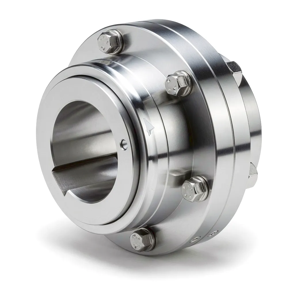 Thermal power stations represent one of the most mechanically demanding environments in all of industrial engineering. In a coal-fired or gas-fired generating facility, the steam turbine and electrical generator are connected across a single driveline that must transmit hundreds of megawatts of power without interruption, often for continuous periods measured in months rather than days. The coupling placed between these two rotating machines is therefore not a peripheral component — it is the mechanical centrepiece of the entire generating set. Britain’s thermal power infrastructure, including facilities across the Midlands, Yorkshire, and the North East, relies on shaft couplings that can absorb axial growth from thermal expansion, suppress torsional vibration, and maintain dynamic balance at rotational speeds that can exceed 3,000 rpm.
What makes this application uniquely challenging is the combination of factors that act simultaneously. High rotational speed generates centrifugal stresses that compound fatigue loading. Continuous operation over years rather than weeks rules out any maintenance cycle that requires turbine shutdown. Thermal gradients across a running turbine shaft cause measurable radial and angular displacement at the coupling interface, creating dynamic misalignment that a rigid connection simply cannot tolerate. Understanding why specific coupling types are selected for thermal power drives — and how they are engineered to cope with these conditions — is essential knowledge for any mechanical or rotating equipment engineer working in the UK energy sector.
Working Principle of Couplings in Turbine-Generator Sets
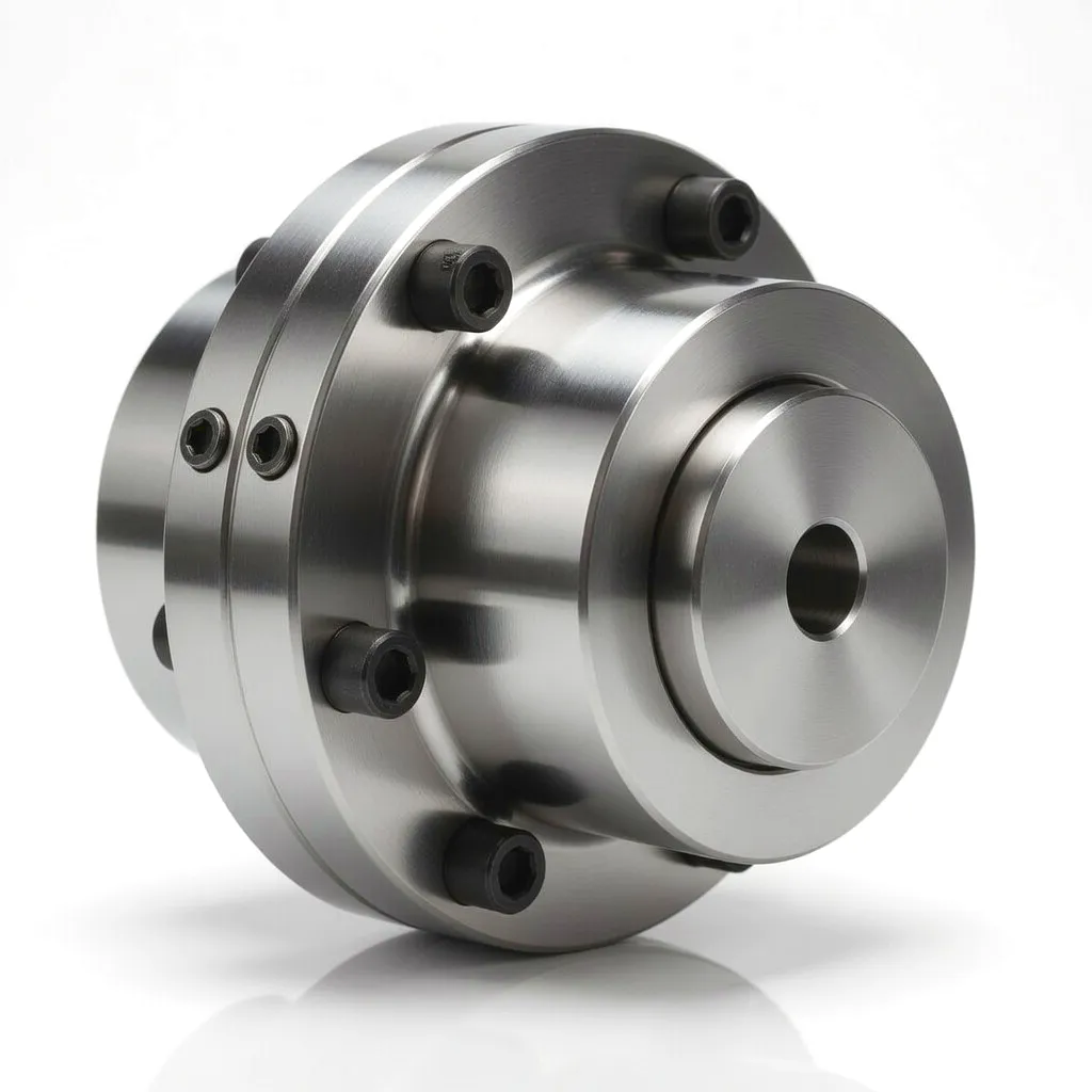 At its most fundamental level, a coupling in a thermal power driveline performs three simultaneous mechanical tasks: it transmits the torque produced by the steam turbine to the generator rotor, it accommodates the physical misalignment between the two shaft centrelines, and it protects both machines from sudden shock loads or torsional impulses that could damage their bearings or windings. In a large steam turbine driving a generator at 3,000 rpm — the standard synchronous speed for 50 Hz grid-connected generation in the United Kingdom — the coupling must handle torques that can reach several hundred kilonewton-metres under full load.
Gear-type couplings are particularly well suited to this role because of their inherent flexibility. Each hub is machined with external gear teeth that mesh with internal teeth in a surrounding sleeve. As the shaft centre migrates due to thermal expansion, the gear mesh can accommodate both angular misalignment (typically up to 1.5° per gear mesh) and axial displacement without transmitting bending moments back into the shaft bearings. This tooth-to-tooth sliding action is lubricated with a specially formulated high-temperature grease or oil, which allows continuous relative motion without fretting wear.
Disc couplings operate through an entirely different mechanism. Multiple thin metallic discs are arranged in a pack and bolted alternately to the driving and driven flanges. Torque is transmitted through the in-plane tension and compression stiffness of the disc pack, while angular and axial misalignment is accommodated by the elastic bending of the discs. Because there are no sliding surfaces, disc couplings are inherently maintenance-free and do not require lubrication — a compelling advantage in high-availability power generation where any unscheduled outage carries enormous cost implications.
Core Materials: Alloy Steels & High-Performance Metals
The hub bodies and sleeves of gear-type couplings used in thermal power applications are almost universally machined from low-alloy structural steels such as 42CrMo4 or 34CrNiMo6, selected for their excellent combination of tensile strength, toughness, and fatigue resistance. After rough machining, hubs are typically carburised and case-hardened to achieve a tooth surface hardness of HRC 58–62, which resists the micro-pitting and fretting damage that would otherwise shorten service life in continuous-duty applications.
For generator sets operating at particularly high speeds or in environments where weight reduction is critical — as is increasingly common in combined-cycle gas turbine (CCGT) plants — titanium alloy hubs or aluminium alloy intermediate shafts are sometimes specified. These materials offer specific strength values that allow designers to reduce coupling mass while maintaining the fatigue margin demanded by power generation standards.
Disc Coupling Materials: Stainless Steel & Composite Alloys
The disc packs in disc couplings are typically manufactured from precipitation-hardened stainless steels such as 17-4PH or 15-5PH. These alloys achieve tensile strengths exceeding 1,000 MPa while retaining sufficient ductility to withstand the cyclic bending loads imposed by angular misalignment. The stainless composition also provides inherent corrosion resistance, which is beneficial in coastal power stations or facilities where condensate from steam pipework creates a humid microenvironment around the coupling.
Fasteners and flanges are typically manufactured from heat-treated alloy steels, and all mating surfaces are finished to tight tolerances to ensure uniform load distribution across the disc pack. Some manufacturers apply ceramic-based coatings to high-contact areas to reduce fretting fatigue at the disc-to-flange interface — a detail that significantly extends service life in high-duty cycling applications.
Core Technical Advantages for Thermal Power Drive Applications
Gear-type couplings designed for large turbine-generator sets routinely handle torques exceeding 500 kN·m, with peak overload ratings that provide a safety margin for grid fault events such as short-circuit torque surges.
When a turbine heats from cold start to full operating temperature, the shaft can grow by several millimetres axially and shift radially by fractions of a millimetre. Gear and disc couplings absorb this movement without transmitting damaging bending loads into turbine or generator bearings.
Through optimised tooth geometry, case hardening, and precision dynamic balancing to G2.5 grade, power generation couplings achieve cumulative service lives exceeding 100,000 operational hours — matching or surpassing the major overhaul intervals of the machines they connect.
All rotating coupling assemblies are balanced to G2.5 grade or better per ISO 1940-1 as standard. Higher balance grades such as G1.0 are available for ultra-high-speed turbine applications where residual unbalance would cause unacceptable vibration levels on sensitive generator bearings.
Disc couplings are fully lubrication-free. Gear couplings, when supplied with modern synthetic high-temperature grease and sealed retainers, can meet regreasing intervals of 25,000 hours or more — significantly reducing the maintenance burden on power station engineering teams.
During grid disturbances, synchronised generators can experience instantaneous torque reversals many times the rated load. The elastic compliance of disc packs and gear tooth backlash absorb these transients before they can propagate into the turbine’s last-stage blades or the generator’s shaft end-rings.
Product Technical & Performance Parameter Table
| 매개변수 | Gear-Type Coupling | 디스크 커플링 |
|---|---|---|
| 정격 토크 범위 | 10 to 2,000 kN·m | 5 to 800 kN·m |
| 최대 속도 | Up to 5,000 rpm | Up to 30,000 rpm |
| 각도 불일치 | Up to 1.5° per mesh | Up to 1.0° per element |
| 축 방향 변위 | ±5 to ±25 mm | ±1 to ±5 mm |
| 허브 소재 | 42CrMo4 / 34CrNiMo6 | 42CrMo4 / Ti Alloy |
| Disc / Sleeve Material | Alloy steel, case-hardened HRC 58–62 | 17-4PH / 15-5PH Stainless |
| 동적 균형 등급 | G2.5 표준 / G1.0 선택 사양 | G2.5 표준 / G1.0 선택 사양 |
| 작동 온도 | -20 °C to +120 °C | -50 °C to +300 °C |
| Service Life Target | > 100,000 hours | > 100,000 hours |
| Lubrication Requirement | High-temp grease / oil; 25,000 hr interval | None (maintenance-free) |
| Overload Capacity | 2.0× rated torque (momentary) | 3.0× rated torque (momentary) |
Industrial Application Scenarios: Thermal Power Generation Drive Systems
Steam Turbine to Generator Coupling — Large Coal & Gas Power Plants
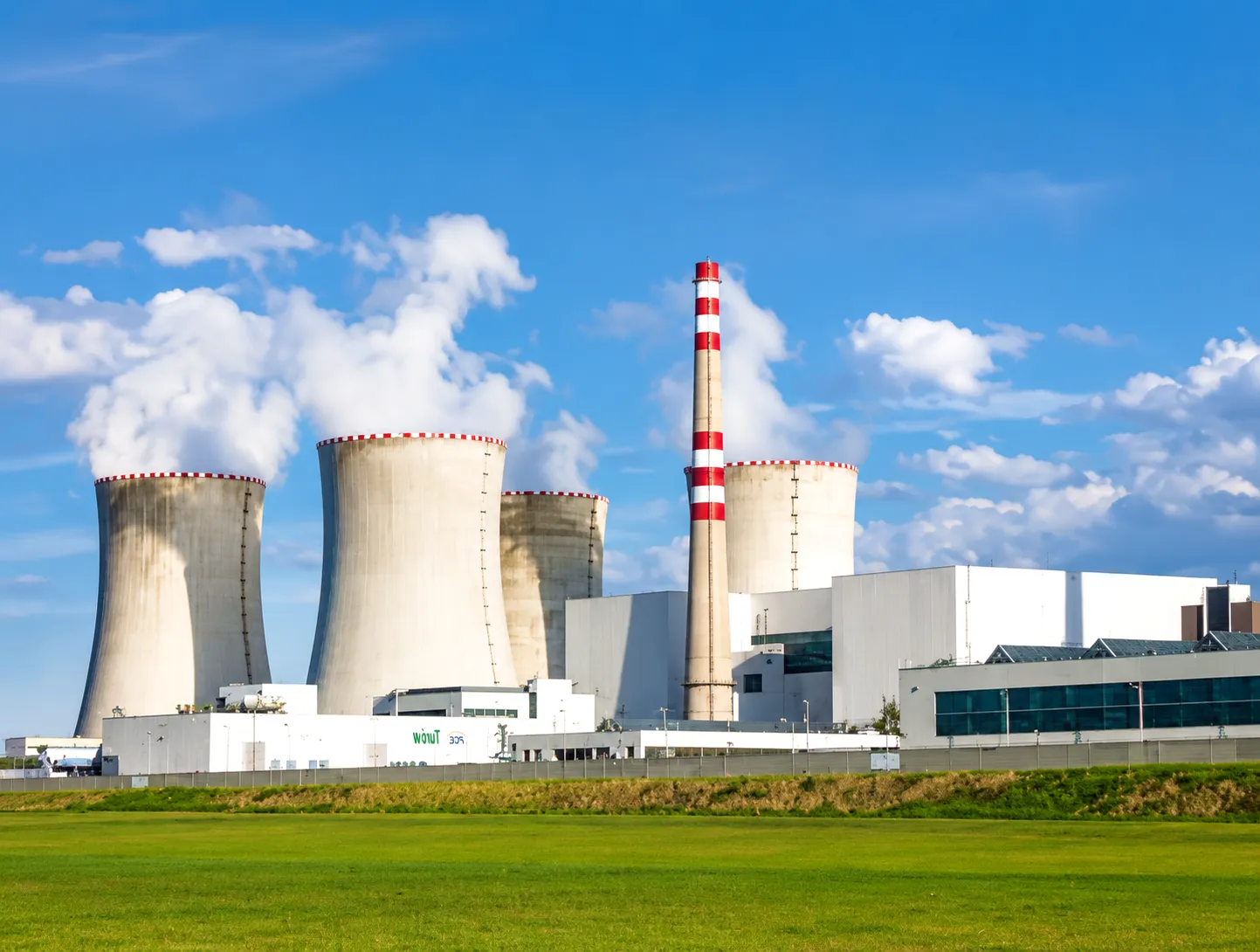 In conventional coal-fired stations — including those that continue to operate across the UK’s East Midlands and Yorkshire regions — the main steam turbine is typically a multi-stage machine with intermediate-pressure and low-pressure stages arranged on a common shaft. This shaft drives directly into the generator rotor, and the coupling between them must transmit the full output of the machine, which can run to 660 MW or more in modern supercritical units. Gear-type couplings installed in this position must not only carry the steady-state torque but must also survive the transient overloads that occur during grid reconnection after a trip, when the generator is suddenly resynchronised with the live network. The resulting torque spikes can reach two to three times the rated load and last for several seconds — an extreme fatigue event that design engineers must account for in the fatigue analysis of every coupling component.
Beyond structural integrity, the coupling in a large turbine-generator set also plays a critical role in the torsional dynamics of the entire shaft train. Any natural torsional frequency that falls within the range of excitation frequencies produced by the electrical network — typically 0–50 Hz and its harmonics — can lead to sub-synchronous resonance, which has caused catastrophic shaft failures in large generating units worldwide. Precision-engineered couplings with carefully calculated torsional stiffness values allow rotating equipment engineers to tune the shaft train’s natural frequencies away from dangerous excitation bands.
Combined Cycle Gas Turbine (CCGT) Plants — High-Speed Disc Coupling Applications
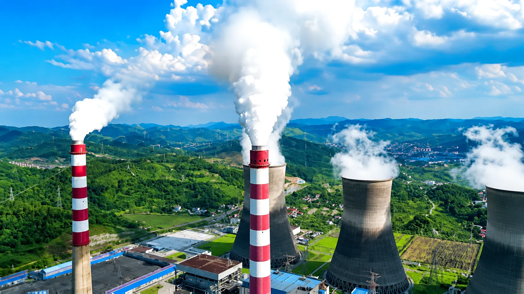 Combined cycle gas turbine plants have become the backbone of UK gas-fired power generation, with major installations operating across locations from Pembroke in Wales to Seabank in South Gloucestershire and Keadby in North Lincolnshire. In a CCGT plant, the gas turbine typically drives the generator at speeds between 3,000 and 3,600 rpm, but the hot exhaust gases then pass through a heat recovery steam generator (HRSG) to drive a steam turbine on a separate, co-axial shaft train. Disc couplings are the preferred choice for CCGT applications because they eliminate the lubrication requirements of gear couplings — a significant operational advantage when the coupling is located in the hot gas path section where access for maintenance is severely restricted by the surrounding thermal insulation and structural steelwork.
The relatively compact physical envelope of disc coupling assemblies also makes them easier to incorporate into the tight space constraints of modern CCGT turbine halls, where the desire to maximise power density in a given footprint has progressively reduced the physical separation between machines. Disc packs fabricated from 17-4PH stainless steel can withstand the elevated temperatures experienced in gas turbine exhaust zones without degradation of mechanical properties, and their inherently low windage losses at high speeds contribute to the marginal improvements in overall plant efficiency that power generators continuously seek to improve their capacity market competitiveness.
Boiler Feed Pump Drive Trains — Auxiliary Coupling Applications
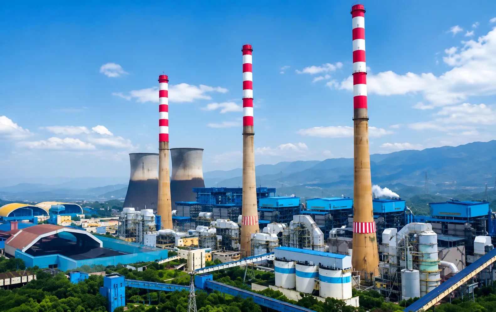 The boiler feed pump is arguably the most critical auxiliary machine in any thermal power station. Running continuously to maintain the precise flow of high-pressure feedwater into the boiler, these pumps are typically driven either directly by a steam turbine or through a fluid coupling and gearbox arrangement connected to a large electric motor. In either case, the coupling between the driver and the pump must accommodate the speed changes that occur as flow demand fluctuates with load dispatching, and must absorb the hydraulic shock loads that occur when the pump trips and valves slam shut. Gear-type couplings are widely used in boiler feed pump drive trains across UK power stations because of their proven ability to handle these conditions over very long service intervals without requiring extensive condition monitoring.
Planned maintenance windows at UK power stations are typically short and infrequent — increasingly so as the grid depends on dispatchable thermal plant to balance intermittent renewable output. A boiler feed pump coupling that requires regreasing or inspection every few thousand hours represents a significant operational burden. Modern sealed gear couplings filled with synthetic extreme-pressure grease, or maintenance-free disc coupling alternatives, are therefore strongly preferred by maintenance engineers seeking to extend the intervals between planned outages and reduce the volume of work scheduled into each shutdown period.
Induced Draft Fan & Cooling Tower Drive — Flexible Coupling in Continuous Service
 Induced draft fans and cooling tower fans are among the largest continuously running rotating machines at any thermal power station. At a typical UK plant, induced draft fans can draw up to 5 MW of installed power, running 24 hours a day throughout the generating season. These fans are driven through gearboxes connected to large electric motors, with a coupling on both the input and output side of the gearbox. The coupling on the motor input side must tolerate the high starting torques generated by the motor before it reaches synchronous speed — an event that imposes very different demands on the coupling from its steady-state operating conditions.
At plants located on coastal sites or near rivers — as is common in the UK, where cooling water availability has historically determined power station locations — induced draft fan drive trains also operate in environments with elevated moisture and salt content in the ambient air. Couplings in these locations benefit from surface treatment packages that include phosphating, epoxy painting, and stainless fasteners to resist corrosive attack between scheduled maintenance interventions.
Featured Coupling Products for Power Generation
유연 빔 커플링
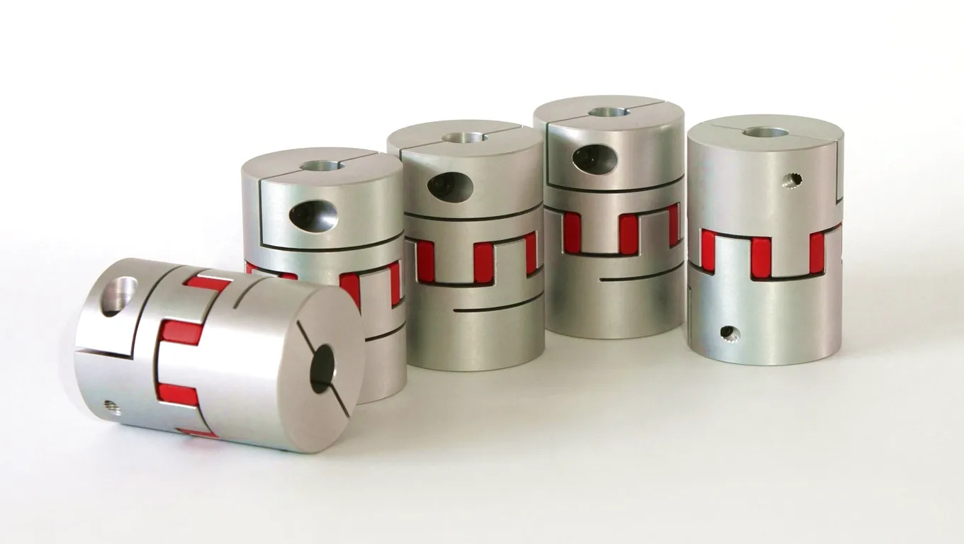
The Flexible Beam Coupling from Ever Power is a helical-cut single-piece coupling machined from aircraft-grade aluminium alloy. The helical slots in the body create a spring-like flexible element that accommodates angular and parallel misalignment with zero backlash. This makes it an ideal choice for auxiliary drives in power station control systems, instrument drive applications, and precision actuator linkages where positional accuracy and torsional responsiveness both matter. With operating speeds up to 10,000 rpm and a torque range from 0.2 to 12 N·m, the Flexible Beam Coupling suits instrumentation and servo applications throughout the power generation environment.
디스크 커플링
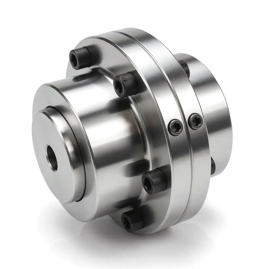
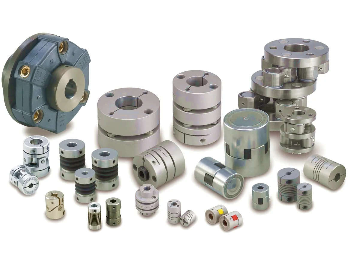
Ever Power’s Disc Coupling range is engineered for the most demanding high-speed, high-torque power transmission environments, making it a natural fit for CCGT and steam turbine generator applications across the UK energy sector. Fabricated from stainless steel disc packs arranged in precision-ground alloy steel spacer and flange assemblies, the disc coupling transmits torque through the in-plane tension of the disc elements while absorbing angular and axial misalignment through elastic disc bending — entirely without lubrication. With zero-maintenance operation, wide temperature compatibility, and dynamic balance to G2.5 or better, the Disc Coupling is the first choice for power station engineers seeking to extend planned outage intervals and reduce lifecycle maintenance costs on turbine-generator drive trains.
Ever Power: Precision Coupling Manufacturing & Customisation for UK Energy Projects
Ever Power has spent decades refining its manufacturing processes for power generation couplings, building a product range that covers everything from small-bore beam couplings for instrumentation drives through to massive gear-type assemblies capable of transmitting multi-megawatt turbine outputs. The manufacturing facility operates precision CNC turning, milling, and gear hobbing centres with tolerances maintained to IT5 or better on all critical dimensions. Every coupling destined for thermal power applications is inspected using coordinate measuring machines (CMM) and subjected to full dynamic balancing on purpose-built balancing machines calibrated to ISO 1940-1 Grade G2.5 or better as standard.
What truly distinguishes Ever Power in the UK market is the depth of our customisation capability. No two power generation projects are identical: shaft diameter tolerances, keyway configurations, coupling spacer lengths to accommodate maintenance access requirements, special surface treatment specifications, and the torsional stiffness values demanded by shaft train dynamic analysis all vary from project to project. Ever Power’s engineering team collaborates directly with rotating equipment engineers at UK power generation projects, providing torsional analysis support, material certification packages to meet UKCA and CE marking requirements, and expedited delivery programmes for critical plant replacement parts that cannot wait weeks for standard lead times.
Nottinghamshire CCGT Plant Eliminates Coupling-Related Outages with Ever Power Disc Coupling Retrofit
 A 900 MW combined cycle gas turbine station in the Trent Valley region of Nottinghamshire had been experiencing recurring unplanned shutdowns attributable to lubrication failure in the gear-type couplings fitted to its gas turbine drive trains. The couplings, which had been in service since the station’s commissioning, were reaching the end of their designed regreasing interval, but the operational tempo of the plant — under pressure from the UK capacity market to maximise availability during winter demand peaks — left insufficient scheduled downtime to carry out the required maintenance. The result was a pattern of bearing distress in the gas turbine driven end, triggered by dry-running in the gear coupling teeth, leading to elevated vibration alarms and ultimately trips that removed the unit from service at commercially damaging moments.
The plant’s rotating equipment team engaged Ever Power to design a retrofit disc coupling solution that could be installed during a planned summer maintenance window. Ever Power’s engineers conducted a torsional analysis of the existing drive train, confirmed that the torsional natural frequencies of the proposed disc coupling configuration were safely removed from the network excitation frequencies, and produced a set of custom disc coupling assemblies with spacer lengths matched to the existing turbine-to-generator shaft separation. The hubs were manufactured from 42CrMo4 to match the turbine shaft material, and the disc packs were produced from 17-4PH stainless steel with a fatigue analysis confirming a service life in excess of 120,000 hours at the design torque and misalignment values.
The retrofit was completed within the planned five-day window, with no additional outage time required. In the eighteen months following the installation, the unit recorded zero unplanned trips attributable to the drive train coupling, and the station’s maintenance team confirmed that the planned inspection interval for the disc coupling assemblies extended the coupling maintenance schedule from the previous 8,000-hour regreasing cycle to a 40,000-hour visual inspection schedule — dramatically reducing both the maintenance workload and the risk of forced outage during high-price dispatch periods.
“Ever Power’s disc coupling retrofit has been transformative for our availability record. Eighteen months of clean operation after we’d been battling coupling-related trips for two years. The quality of the engineering documentation they provided for our maintenance management system was equally impressive.”
“We specified Ever Power for the disc coupling on our new boiler feed pump drive after reviewing several suppliers. What set them apart was their willingness to carry out the torsional stiffness calculations to our shaft train model inputs rather than just providing off-the-shelf data sheets. The couplings have been in continuous service for over two years without any issues.”
“Delivery lead time on a custom-bore gear coupling for our induced draft fan drive was six weeks from enquiry to delivery — which is exceptionally fast for a fully customised part. The material certification pack was complete, and the balance certificates were spot on. Our inspection team signed off without any queries. Ever Power will be our first call for any future coupling requirement.”
Frequently Asked Questions: Couplings for UK Thermal Power Generation
Ready to Specify the Right Coupling for Your Power Generation Project?
Ever Power’s engineering team is ready to support your turbine coupling selection, torsional analysis review, and customisation requirements. Send your project data and we will respond within one working day.