
Industrial Power Transmission · UK Market
Gear Couplings in Industrial Applications: From Paper Mills to Heavy Manufacturing
A technical deep-dive into gear coupling selection, performance parameters, and real-world deployment across the UK’s most demanding industrial environments.
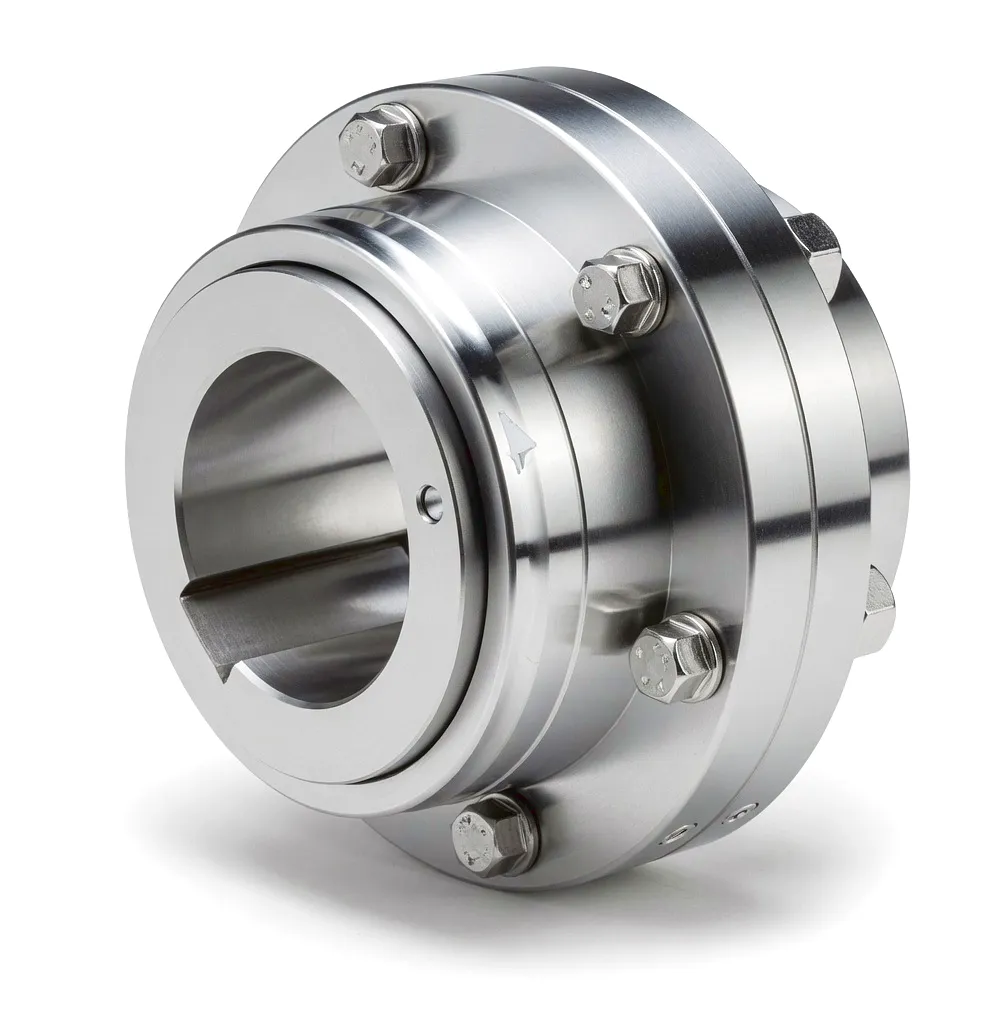 Across the breadth of British industry — from the vast paper mills of Wales and Scotland to the steel fabrication shops of Sheffield, and the marine engineering yards of Tyneside — gear couplings remain one of the most relied-upon mechanical components in rotating machinery. These precision-engineered devices serve a function that might seem deceptively simple on the surface: they connect two shafts to transmit torque while accommodating the inevitable misalignment, thermal expansion, and dynamic loading that real-world machinery generates. In practice, however, getting that function right demands a deep understanding of materials science, mechanical dynamics, and industrial application requirements. The gear coupling’s characteristic design — a pair of hubs with external teeth meshing with internal teeth in a flanged sleeve — gives it the exceptional torque density and misalignment tolerance that have kept it at the heart of heavy-duty drive systems for well over a century. Modern variants have evolved considerably from the original cast-iron units, incorporating hardened alloy steel tooth profiles, precision-machined bores, and lubrication-retaining seals that can sustain continuous operation in aggressive process environments.
How Gear Couplings Work: The Mechanical Principle
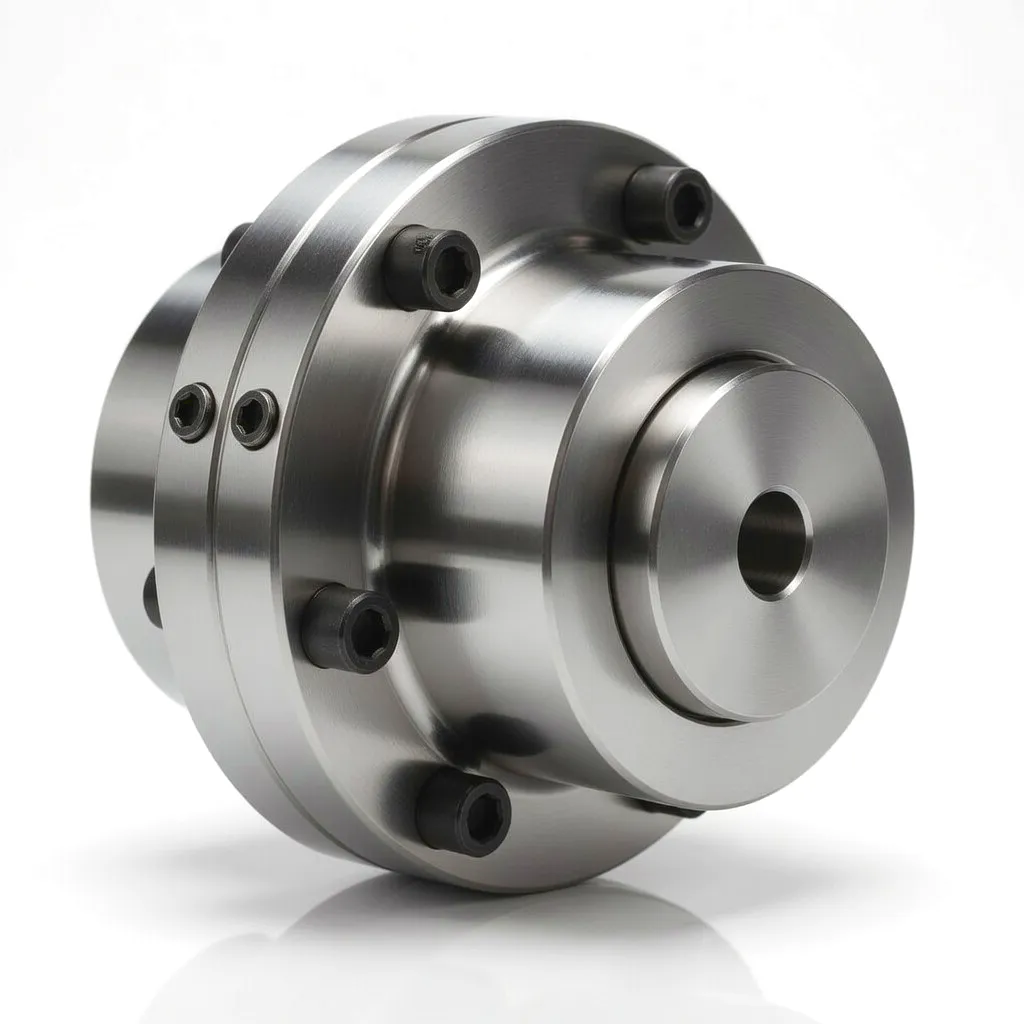 A gear coupling transmits torque through the meshed engagement between crowned external gear teeth on the hubs and straight internal gear teeth on the sleeve halves. The crowning on the hub teeth is the critical geometric feature: it is a barrel-shaped modification to the tooth profile, allowing each tooth to rock slightly within its mating groove when the shaft axes are not perfectly aligned. This rocking motion enables the coupling to accommodate angular misalignment up to approximately 1.5 degrees per gear mesh (and up to 3 degrees in full-flex configurations with two gear meshes), without generating destructive bending stresses at the tooth root or imposing excessive radial loads on connected bearings.
Core Materials in Gear Coupling Manufacturing
Alloy Steel (42CrMo4 / 40Cr)
The hubs carrying the crowned external teeth are invariably machined from medium-carbon alloy steels. 42CrMo4 (equivalent to AISI 4140) is the most widely specified grade, offering a tensile strength of 900–1100 MPa after quench and temper treatment. The alloy’s chromium content provides hardenability in section, ensuring the tooth flanks reach 52–58 HRC after carburising or induction hardening, while the molybdenum addition improves toughness and resistance to temper brittleness. 40Cr is used in lighter-duty ranges. Tooth geometry is finish-ground after heat treatment to achieve profile accuracy in accordance with ISO 1328 Grade 6 or better, which is essential for smooth load sharing across the full mesh at rated torque.
Cast Steel / Ductile Iron Flanged Sleeve
Sleeve halves for standard-range gear couplings are cast from low-alloy steel or high-strength ductile iron (GGG-60/GGG-70 grade), balancing weight with the structural rigidity needed to maintain tooth engagement geometry under bending loads. For high-speed applications above 3,000 rpm, forged steel sleeves are used to minimise residual porosity and withstand the centrifugal stresses that can cause a cast component to fail. The flange mating faces are precision-machined and dowel-located to ensure accurate sleeve halves alignment. Critical dimensions — particularly the pitch circle diameter of the internal teeth — are held to tolerances of ±0.01 mm to guarantee correct crowning engagement with the hub teeth throughout the operating misalignment range.
Neoprene / PTFE Sealing Rings
Grease retention is handled by O-ring or lip seals moulded from neoprene (CR), which remains flexible at temperatures from -40°C to +120°C and resists the petroleum-based lubricants used in most gear couplings. Where process contamination with acidic or chemical vapours is a concern — as in paper mill drive rooms — PTFE-faced seals or a labyrinth-type non-contact seal arrangement is preferred. Proper sealing is not merely a maintenance convenience; grease loss under dynamic misalignment conditions leads to accelerated tooth wear and can cause the coupling to seize, with potentially catastrophic consequences for connected equipment. Seal replacement intervals are typically set at 12 to 24 months, depending on operating speed and temperature.
316L Stainless Steel (Food & Marine)
For drives in food processing, offshore marine, and pharmaceutical environments, 316L austenitic stainless steel hubs and sleeves are available. This grade’s 2% molybdenum addition provides resistance to chloride pitting corrosion, which is particularly important in the coastal manufacturing areas of the UK such as Hull, Grimsby, and the Firth of Forth. While stainless steel offers lower hardenability than alloy steel — meaning tooth surface hardness is typically limited to around 35–40 HRC via nitriding — the trade-off of improved corrosion resistance is essential in environments where carbon steel would corrode within weeks. The tooth geometry for stainless variants uses slightly deeper crowning to compensate for the reduced surface hardness, maintaining the coupling’s rated torque capacity at the expense of a modest increase in coupling weight.
Technical Advantages of Gear Couplings
01
Superior Torque Density
The distributed tooth contact mechanism allows gear couplings to transmit substantially higher torques per unit mass and per unit bore diameter than most other flexible coupling types. In applications where weight or envelope constraints are critical — such as in rolling mill main drives or ship propulsion shafting — this advantage directly translates to a more compact and cost-effective drive train design. Rated torque values for standard series gear couplings range from as low as 150 Nm for small precision units to in excess of 6,000,000 Nm for the largest marine and rolling mill units, covering an extraordinary breadth of industrial applications within a single coupling technology family.
02
Tolerantie voor verkeerde uitlijning
Angular misalignment accommodation up to 1.5° per mesh, and parallel offset accommodation that scales with spacer length, makes gear couplings uniquely suited to drive trains where thermal growth between hot and cold states generates significant shaft displacement. In paper machine drives operating at process steam temperatures, the frame and bearing housings expand differentially during the heat-up period, and a gear coupling that can absorb this movement without generating bearing-damaging reaction forces is critical to machine availability. The misalignment capacity is not a one-time tolerance but a continuous operating capability, meaning the coupling can work at or near its rated misalignment angle throughout its service life without performance degradation.
03
High Speed Capability
Precision-balanced gear couplings can operate at pitch line velocities exceeding 60 m/s, making them suitable for high-speed turbine drives, centrifugal compressor trains, and the high-speed sections of modern paper machines running at 2,000 m/min or more. Achieving these speeds safely requires careful attention to the dynamic balance grade (ISO 1940 G2.5 or better), precision of the tooth mesh, and the concentricity of the assembled coupling on the shaft. Oil-lubricated variants with spray nozzles directed into the tooth mesh area manage the heat generated at high sliding velocities, maintaining oil film thickness on the tooth flanks and preventing metal-to-metal contact even under peak torque transients.
04
Torsional Rigidity
Unlike elastomeric couplings, gear couplings transmit torque through a rigid metallic tooth mesh, providing a torsional stiffness that does not degrade with temperature, chemical exposure, or fatigue cycles. This makes them the preferred choice in servo-positioning and web tension control applications where angular lag between motor and load must be minimised. In a paper machine winder or coater drive, even a small amount of torsional wind-up in the coupling would generate unacceptable variation in web tension, causing web breaks and quality defects. The predictable and constant torsional characteristic of the gear coupling simplifies drive system modelling and control loop tuning, reducing commissioning time and improving the stability of closed-loop tension control systems.
Product Technical & Performance Parameters
The table below summarises the typical performance envelope of standard and heavy-duty gear coupling series suitable for UK industrial applications. Exact values for any specific coupling size should be confirmed with the manufacturer’s published catalogue or via a bespoke application calculation.
| Parameter | Standard Series | Heavy Duty Series | High-Speed Series | Spacer Series |
|---|---|---|---|---|
| Nominaal koppel (Nm) | 150 – 500,000 | 500,000 – 6,000,000 | 150 – 250,000 | 200 – 2,000,000 |
| Max. Angular Misalignment | 1,5° per maaswijdte | 1,0° per maaswijdte | 0.75° per mesh | 1,5° per maaswijdte |
| Max. Parallel Offset (mm) | Up to 6 | Up to 10 | Tot 3 | Tot 25 |
| Max. Operating Speed (rpm) | 3,600 | 1,800 | 12,000 | 3,000 |
| Naafmateriaal | 42CrMo4 / 40Cr | 42CrMo4 Forged | 42CrMo4 Ground | 42CrMo4 / SS316L |
| Tandoppervlaktehardheid (HRC) | 52 – 56 | 54 – 58 | 56 – 60 | 52 – 58 |
| Smeertype | Grease packed | Grease / Oil | Continuous oil | Grease packed |
| Operating Temperature Range (°C) | -30 to +120 | -20 to +150 | -20 to +180 | -30 to +120 |
| Balance Grade (ISO 1940) | G6.3 | G6.3 | G2.5 / G1.0 | G6.3 / G2.5 |
| Diameterbereik van de boring (mm) | 16 – 250 | 100 – 650 | 16 – 200 | 25 – 450 |
Application Scenario 1: Paper Machine Drive Systems
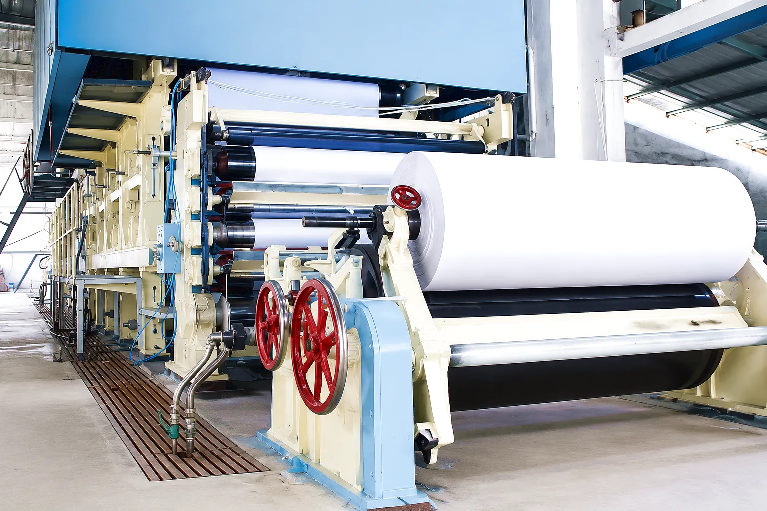 Paper machines represent one of the most demanding environments that any gear coupling can be asked to work in, combining high process speeds, aggressive moisture, strict speed synchronisation requirements, and an operational philosophy built around continuous running with minimal planned stoppages. A modern fourdrinier or twin-wire forming machine is a long assembly of independently driven sections — the wire section, press section, dryer section, size press, and calendar — connected in a series that can extend for 150 metres or more. Each section must be driven at a precisely controlled speed ratio to maintain the paper web under the correct tension as it gains strength and dries along the machine. The drives for each section are typically a motor, a gearbox, and a gear coupling connecting the gearbox output to the roll shaft. The gear coupling in this position accommodates the misalignment between the gearbox output bearing and the roll bearing housing, both of which shift during thermal warm-up and under the roll deflection loads imposed by web tension and press nip pressure.
Modern high-speed paper machines running at press section speeds exceeding 2,000 m/min require gear couplings that have been dynamically balanced to G2.5 or better. At these speeds, even a small residual unbalance in the coupling generates vibration forces that exceed the structural load rating of the roll bearings, causing rapid deterioration and unwanted paper quality variation through periodic basis weight and caliper fluctuations. The tooth profile accuracy of couplings at these speeds must be held to ISO 1328 Grade 5 or better, ensuring that any transmission error as the teeth cycle through mesh is small enough not to excite the natural frequency of the roll-shaft system. Spacer-type gear couplings are commonly specified for paper machine press section drives, where the requirement to withdraw rolls for re-grinding without disturbing the motor or gearbox positions makes the removal of a spacer element, rather than the entire coupling assembly, a significant maintenance time saving. A mill with twenty or thirty press rolls can save multiple days of shutdown time per year by using spacer couplings rather than close-coupled designs.
⚠ The paper machine dryer section introduces a further complication: the drive rolls and cylinders run at elevated temperatures, and the thermal expansion of the cylinder journals relative to the cold gearbox output shafts generates continuous cyclic misalignment as the machine heats up each morning and cools on weekend shutdowns. A gear coupling selected for a dryer section drive must have a misalignment rating that covers the full range of misalignment from cold start to hot steady-state, with adequate margin to allow for foundation settlement and bearing wear over the projected five to ten year coupling service life. Undersized couplings that operate at or near their misalignment limit experience accelerated tooth wear and grease degradation, ultimately failing at a shutdown-critical moment. Engineering teams at UK mills increasingly use thermal FEA of the dryer section frame to calculate the precise misalignment trajectory, allowing the gear coupling selection to be made on a quantified rather than estimated basis.
Application Scenario 2: Steel Rolling Mill Main Drives in Sheffield
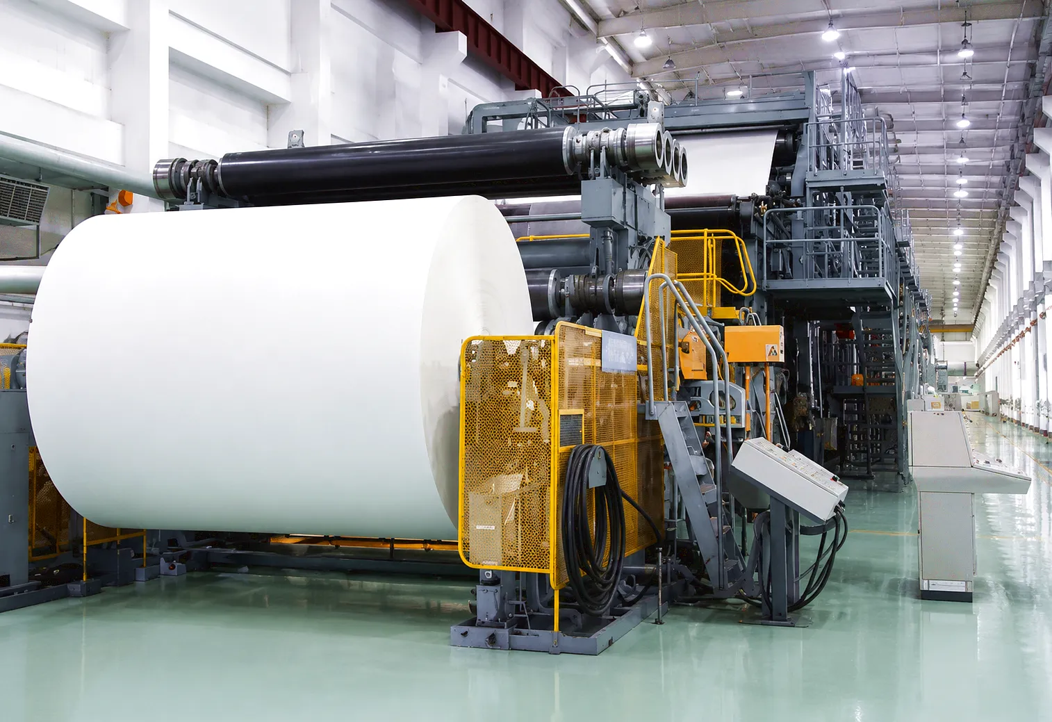 Sheffield’s legacy as a centre of UK steel production continues to demand high-performance gear couplings in rolling mill main drives, where the mechanical loads are among the most severe encountered in any rotating machinery application. In a hot strip mill or plate mill, the drive coupling must transmit the full rolling torque from the main drive motor through a speed-reduction gearbox to the roll pinion stand, and from the pinion stand through spindle couplings to the work rolls themselves. The spindle gear couplings in this position operate at high misalignment angles — typically 3° to 5° continuous — because the roll gap must be adjusted dynamically during rolling to control the strip thickness, and this gap adjustment changes the vertical position of the work roll journals relative to the fixed pinion stand output shafts. The coupling must sustain these high misalignment angles continuously while transmitting shock torques that can exceed five times the nominal motor torque when the slab bites into the roll gap.
Application Scenario 3: Marine Propulsion Shafting on the Tyne
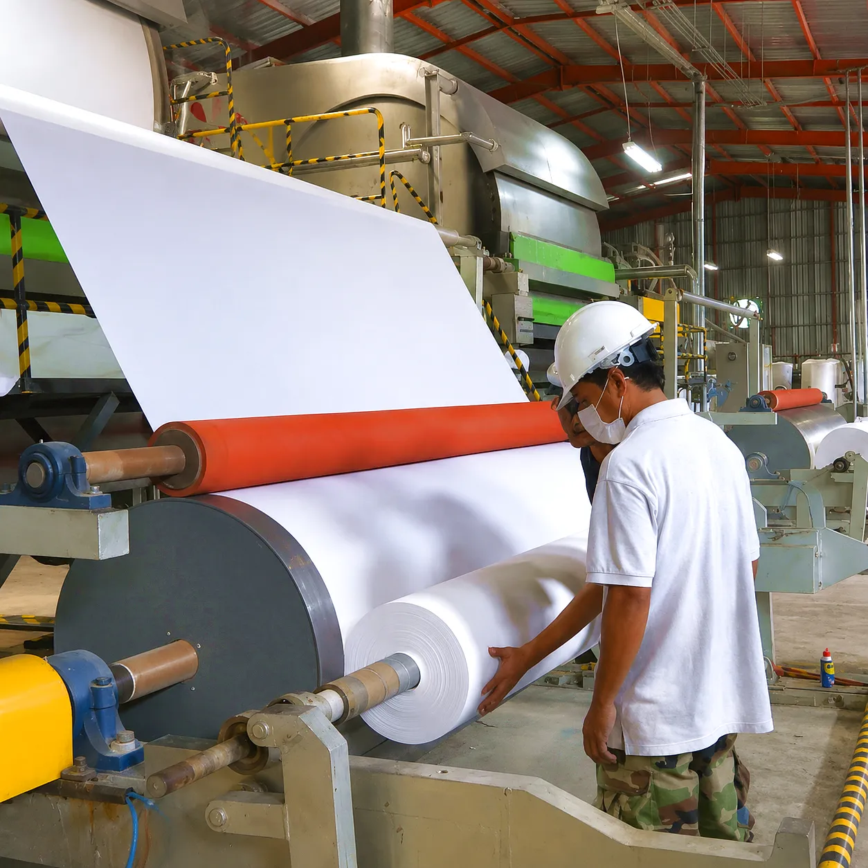 The shipyards and marine engineering workshops of the Tyne corridor in northeast England have a long association with gear couplings in propulsion shaft applications. Marine propulsion shafting connects the main engine or electric motor to the propeller shaft via a series of intermediate shafts supported by plummer block bearings, and the gear couplings at the flange joints between shaft sections serve to accommodate the deflection and angular displacement that occur when the ship’s hull flexes under wave loading. The marine environment imposes stringent material requirements — hull water ingress and salt air create a highly corrosive atmosphere within the shaft tunnel, and any bare steel surface will oxidise rapidly without adequate protection. Marine gear couplings are typically finished with high-build epoxy primer and topcoat, or in demanding cases with thermally sprayed aluminium coatings, supplemented by sacrificial zinc anode fitting to the coupling flange to provide cathodic protection.
Application Scenario 4: Mining & Bulk Handling Conveyors in the Midlands
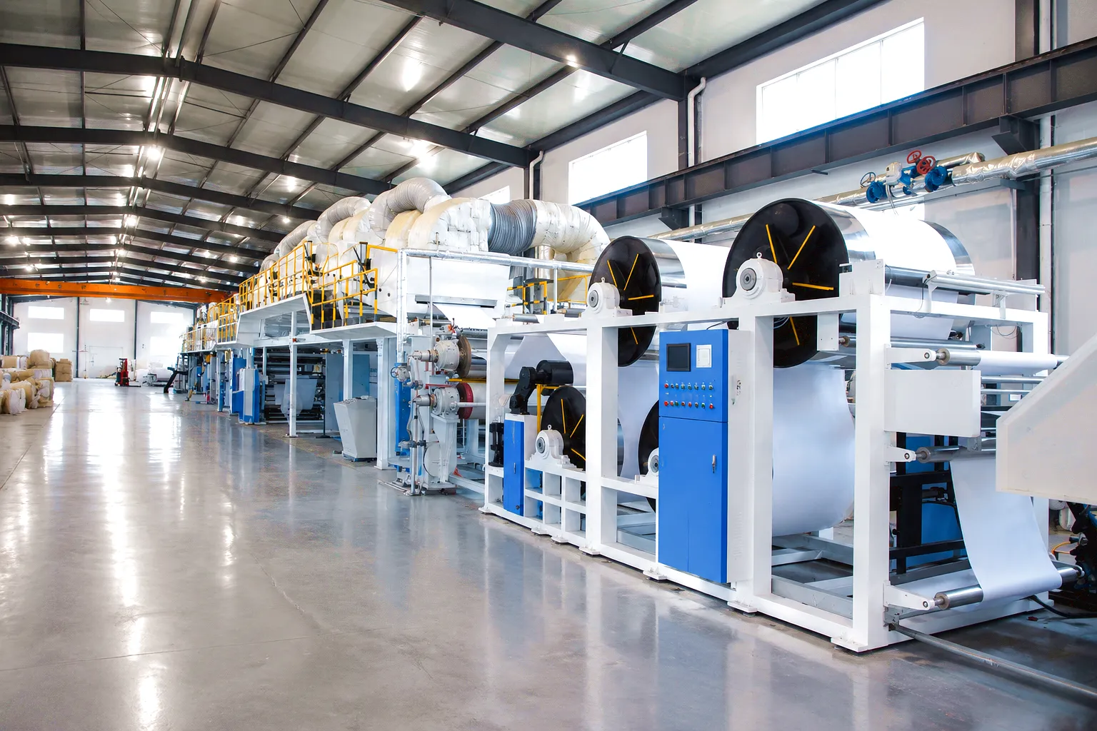 The aggregates processing and bulk materials handling operations of the English Midlands and the quarrying districts of the Peak District and Derbyshire rely heavily on gear couplings in conveyor drives, crusher drives, and bucket elevator mechanisms. These applications share a common characteristic: they are exposed to abrasive dust, often in combination with moisture, and they are subject to frequent high-torque starts as loaded conveyors or crushers are brought online. The start torque can be three to five times the running torque, and in some crusher drive applications, blocked-chute events generate torque peaks that approach the coupling’s ultimate strength. The gear coupling’s metallic construction gives it an inherent peak torque capability that elastomeric or disc couplings simply cannot match without a significant size increase, making it the standard choice for high-power crusher and mill drives throughout the UK mining and quarrying industry.
Application Scenario 5: Centrifugal Pump & Compressor Trains in North Sea Support Industries
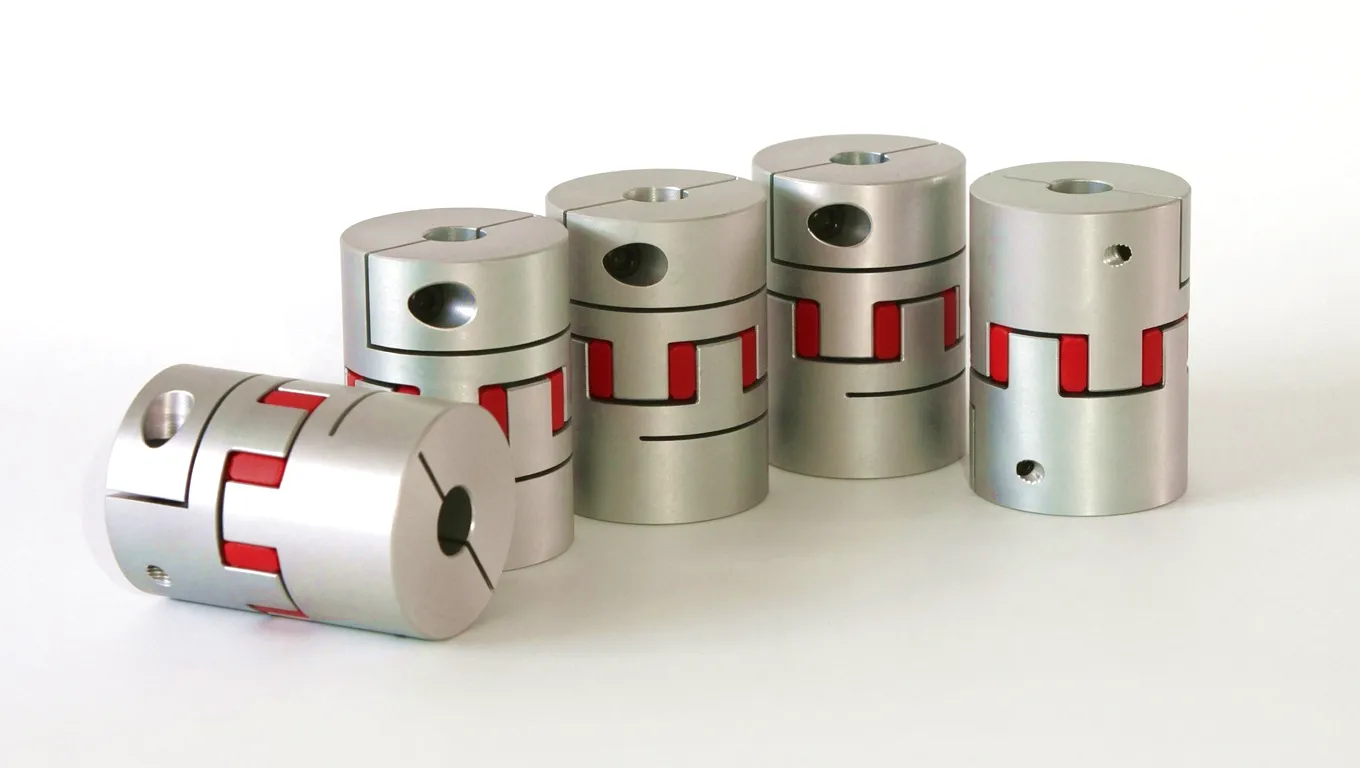 The onshore support and fabrication facilities serving the North Sea oil and gas industry — concentrated around Aberdeen, Montrose, and the Humberside ports — represent a high-value market for precision gear couplings in pump and compressor drives. These drives are characterised by high running speeds (typically 3,000 to 8,000 rpm for centrifugal compressors), continuous duty profiles, and the requirement for zero-leak operation in environments where any process fluid release creates safety or environmental hazard. Gear couplings in compressor train applications are normally the high-speed oil-lubricated variant, where gear oil at controlled temperature and pressure is delivered to the tooth mesh cavity via drillings in the coupling hub, maintaining a hydrodynamic film on the tooth flanks at all operating conditions. The oil supply is normally taken from the compressor’s own lube oil system, ensuring that coupling oil temperature is always within the correct range and that the oil quality is maintained by the compressor’s oil conditioning skid.
The dynamic balance requirement for compressor train gear couplings is the most stringent encountered in any coupling application: balance grade G1.0 or better is routinely specified for couplings running above 6,000 rpm, requiring purpose-built balancing machines capable of measuring and correcting unbalance at the microgram level. The coupling must also be stiff enough torsionally that it does not participate in any of the torsional natural frequencies of the motor-compressor drive train within the operating speed range, a requirement that is verified by a torsional vibration analysis performed before the coupling is selected. The spacer element length in compressor train gear couplings is often optimised as part of the torsional analysis, adjusting the coupling’s moment of inertia contribution to shift the first torsional natural frequency away from potential excitation sources such as motor electrical frequency harmonics or compressor blade passing frequency.
Featured Related Products
Along with our full range of gear couplings, Ever Power supplies precision PTO gearboxes widely used in agricultural and industrial power take-off applications. Two of our most popular models are shown below.
HC-RC31 PTO Gearbox
The HC-RC31 is a robust right-angle PTO gearbox engineered for demanding agricultural and industrial power take-off applications. Built to withstand high input torques, it features a precision-cut gear set, sealed bearing arrangement, and a compact cast housing that makes it suitable for space-constrained installations. The unit is available in multiple gear ratios and can be coupled to either hydraulic motor or direct tractor PTO shaft inputs, making it versatile across a wide range of field machinery and static installations.
HC-RC30-193 PTO Gearbox
The HC-RC30-193 is a versatile, high-efficiency PTO gearbox unit offering a 1:2.93 speed-increasing ratio, making it ideal for driving high-speed implements from a standard 540 rpm tractor PTO. Its bevel gear design delivers smooth, quiet operation with minimal power loss. The housing is manufactured from high-strength ductile iron for durability in field conditions, and the shaft configuration supports both flange and splined output connections. This model is commonly specified for wood chippers, mulchers, and centrifugal pump drives across UK agricultural operations.
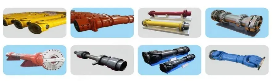
Manufacturing Excellence
Ever Power: Precision Gear Coupling Manufacturing & Customisation
Ever Power operates a dedicated gear coupling manufacturing facility equipped with CNC gear grinding machines, coordinate measuring machines (CMM), dynamic balancing rigs, and full material testing laboratory capabilities. The manufacturing process begins with incoming material certification review — every batch of alloy steel bar is certified to chemical composition and mechanical property requirements before it enters the machining area, ensuring that the properties of the finished coupling are predictable and consistent with the design calculations.
What distinguishes Ever Power in the gear coupling market is not simply the ability to manufacture standard catalogue sizes, but the depth of its engineering customisation capability. UK customers across a range of industries — from paper mills requiring couplings with bespoke spacer lengths and stainless steel construction to rolling mill operators specifying non-standard bore diameters and keyway configurations to fit existing equipment — rely on Ever Power’s engineering team to take their application data and return a coupling design that is optimised for their specific installation. The customisation scope covers all the parameters that matter most to industrial users: bore diameter and tolerance class, keyway specification, hub material and heat treatment, tooth module and crowning radius, flange diameter and bolt pattern, balance grade, and surface finish and coating.
Ever Power’s supply chain advantages include a dedicated raw material buffer stock programme that ensures alloy steel forgings for the most common coupling hub sizes are available for rapid production scheduling, reducing lead times for standard sizes to as little as two to three weeks. For urgent replacement requirements — the kind of situation that arises when a critical coupling fails unexpectedly during a production campaign — Ever Power maintains a rapid response service with dedicated manufacturing slots and air freight logistics capability to UK addresses, ensuring that a custom-manufactured replacement coupling can reach a Birmingham or Sheffield facility within days of the order being placed. The quality management system is certified to ISO 9001, and all gear couplings leave the factory with full documentation including material certificates, dimensional inspection reports, and where required, dynamic balance certificates traceable to national standards.
Customer Success Story: Paper Mill Drive Rehabilitation in Dundee
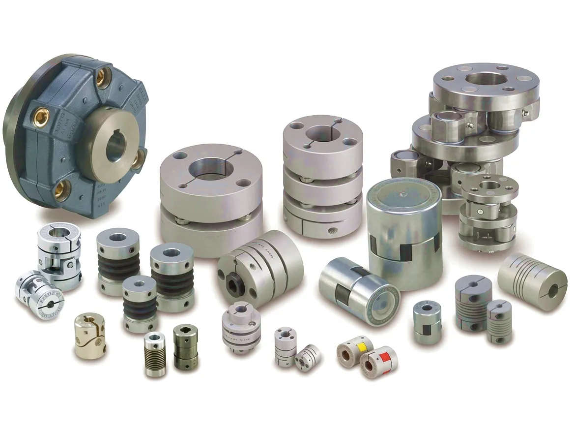 A long-established paper and board manufacturer operating a fourdrinier machine in Dundee, Scotland, had been experiencing recurring gear coupling failures on the press section drives approximately every 14 to 18 months. The failures were characterised by accelerated tooth wear and grease leakage, ultimately leading to coupling seizure and unplanned production shutdowns that typically cost the mill between 18 and 24 hours of lost output per event — a serious financial impact in a market where the mill operated on tight margins and customer delivery commitments.
The mill’s engineering team contacted Ever Power with a detailed description of the failure mode and the operating conditions: press section speed of approximately 1,050 m/min, significant press nip loading causing dynamic roll deflection, a drive room environment with high ambient humidity from steam infiltration, and a maintenance regime that had been unable to maintain the specified annual grease replenishment interval due to labour constraints. Ever Power’s application engineers carried out a site visit to collect firsthand data — measuring the actual shaft alignment under operating conditions using laser alignment equipment, assessing the seal condition on the existing coupling, and reviewing the lubrication records.
The analysis revealed three contributing factors to the failure pattern. The existing couplings had been selected with an angular misalignment rating of 0.75° per mesh, which was insufficient for the actual operating misalignment of 1.1° caused by the thermal growth of the press section frame during the warm-up period. The seal design was a simple O-ring type, which had deteriorated under the combination of steam exposure and the dynamic flexing at the operating misalignment angle, allowing moisture ingress and grease contamination. The lubricant specified in the original design was a standard lithium-based grease, which had inadequate water-resistance for the high-humidity environment.
Ever Power proposed a replacement coupling with a 1.5° per mesh angular rating, a PTFE-faced lip seal with secondary labyrinth geometry, and a formulation switch to a polyurea-based coupling grease with superior water resistance and a 24-month relubrication interval. Bore dimensions and flange configurations were matched exactly to the existing gearbox and roll journal dimensions. The replacement couplings were manufactured and delivered within four weeks, timed to coincide with the mill’s planned Christmas shutdown. Since installation, the Dundee mill has operated through two full annual production cycles without a single coupling-related unplanned stoppage, eliminating the recurring failure cost and recovering an estimated 42 hours of productive machine time that would otherwise have been lost.
★★★★★
“The improvement in coupling service life has been transformational for our press section maintenance budget. Ever Power’s engineers understood our specific failure mechanism from the first conversation, and the replacement couplings have performed without issue through two full production years. The PTFE seal upgrade alone was worth the project. We would not hesitate to recommend them to any UK paper mill dealing with similar wear issues.”
— Senior Mechanical Engineer, Tayside Paper & Board, Dundee
★★★★★
“We specified Ever Power gear couplings for the main drive spindles on our bar rolling mill upgrade in Sheffield, requiring non-standard bore diameters and a very specific flange bolt pattern to match legacy equipment. The engineering team handled the customisation without a single dimensional discrepancy, and the couplings were delivered within our three-week project window. Tooth surface quality under inspection exceeded our drawings’ specification. A thoroughly professional supply experience.”
— Plant Engineering Manager, Hallam Steel Products, Sheffield
★★★★★
“Our compressor train upgrade at the Aberdeen facility required G1.0 balanced gear couplings with oil-lubrication provision and a specific spacer length to satisfy our torsional analysis. Ever Power provided a detailed application review and the required balance certificates with full traceability documentation. The couplings have been running at 6,400 rpm continuously for over eighteen months with vibration levels consistently below our alarm threshold. Exactly what we needed for a safety-critical application.”
— Rotating Equipment Engineer, Caledonian Process Engineering, Aberdeen
Veelgestelde vragen
Ready to Specify Your Gear Coupling?
Contact Ever Power’s engineering team with your application details. We provide free application reviews, detailed quotations, and rapid delivery to all UK locations.
bewerkt door gzl