Description
✔ 20+ Years Manufacturing
✔ Custom Bore & Keyway Options
✔ Full Material Traceability
✔ Export to 40+ Countries
Product Overview

① Weight and moment of inertia are approximate values calculated according to the minimum diameter and maximum length of the shaft hole of the I-type coupling. ② The same type of shaft hole can be arbitrarily combined.
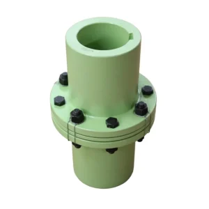
What Is a YL Type Rigid Flange Coupling?
The YL type rigid flange coupling is a bolted flange connector designed to create a permanently stiff, coaxially aligned union between two rotating shafts. Unlike flexible or jaw-type couplings, this design tolerates zero angular or axial misalignment — a requirement that, in practice, compels engineers to prepare and verify shaft alignment with precision tools, and in doing so, guarantees a higher overall drivetrain accuracy and dramatically reduces vibration in sensitive machinery. The coupling consists of two flanged hubs keyed onto each shaft end and fastened face-to-face with a pattern of high-tensile bolts. Torque is transmitted purely through shear forces acting on the bolt group, making the joint extraordinarily stiff and ideal wherever torsional compliance would introduce positioning error, timing drift, or resonance problems in the connected equipment.
In the United Kingdom’s demanding industrial environment — from compressor stations serving North Sea operations to water treatment facilities managed by Thames Water and Anglian Water in East Anglia, to heavy-duty conveyor drives in Yorkshire steel plants — engineers regularly specify the rigid flange coupling wherever power density is high and shaft speeds are moderate. The YL series covers a broad range of bore diameters, with Type I (straight bore) and Type II (tapered bore) hub options available, so that the same coupling body can accommodate different shaft configurations on a single drivetrain. This combinatorial flexibility shortens lead times and simplifies the management of spare-parts holdings in multi-machine facilities where a single maintenance team may be responsible for dozens of rotating assets.
Manufactured from either high-strength HT250 grey cast iron or 45# carbon steel, the YL rigid flange coupling achieves a practical balance between weight, machinability, and structural integrity. All mating flange faces are finish-ground to guarantee perpendicularity between the face and the bore axis. Every production batch undergoes process controls covering raw-material certification, dimensional inspection, surface finish verification, and functional load-path analysis under the ISO9001:2015 quality management system, ensuring that each coupling despatched to a UK customer arrives with complete traceability documentation that satisfies supplier-audit requirements under procurement frameworks such as PAS 55 and ISO 55000.

Why UK Engineers Choose the YL Rigid Flange Coupling
⚙️
Zero-Backlash Transmission
The all-metal flange joint eliminates the elastic play that rubber or polyurethane elements introduce into flexible couplings. This characteristic is critical in servo-driven presses, extruders, printing lines, and precision test-bench dynamometers where positioning repeatability directly determines finished-product quality. UK aerospace and defence supply chain engineers specifically call for zero-backlash couplings to comply with tight component tolerance schedules and traceability mandates.
🔩
Wide Torque Range
YL rigid flange couplings are rated from compact units handling 63 Nm right through to heavy-duty assemblies managing 10,000 Nm and beyond. This makes the series equally at home on a small pump motor shaft and on the output end of an industrial gearbox driving a large centrifugal fan in a combined-heat-and-power plant. With a single product family covering such a wide performance envelope, procurement teams can consolidate their approved supplier lists and reduce the administrative overhead of managing multiple coupling types.
🔄
Flexible Bore Configurations
The YL series supports Type I straight-bore and Type II tapered-bore hub designs, which can be freely combined on the same coupling body. This means a maintenance team can standardise on a single coupling part number while accommodating different shaft diameters on either side of a drive — reducing the range of spares held in stores and accelerating the repair cycle during planned maintenance shutdowns, which is particularly valuable at high-throughput facilities where every hour of downtime carries a measurable production cost.
🛡️
ISO9001-Backed Quality Assurance
Every YL rigid flange coupling leaving the HZPT facility passes documented process controls covering raw-material certification, dimensional inspection, surface finish measurement, and load-path verification under ISO9001:2015. Full traceability from casting or forging through to final despatch is maintained, which directly addresses the supply-chain audit requirements that UK engineering contractors and facility operators increasingly impose on critical rotating component suppliers.
Technical Parameters — YL Series
Representative performance data for standard YL model range. Custom bore diameters, alternative materials (SS304, SS316, ductile iron), and non-standard surface treatments are available on request. Contact our engineering team for a datasheet matched specifically to your application.
 All specifications subject to manufacturing tolerances. Values shown are for standard Type I (straight bore) configurations. Custom keyway dimensions, interference fits (H7/k6, H7/r6), and corrosion-protection coatings are available.
Operating Principle, Materials & Application Scenarios
How the Coupling Transmits Torque
Torque travels from the driving shaft through a keyed or interference-fit hub into the first flange body, across a precision-ground mating face secured by a bolt pattern, and into the second keyed hub on the driven shaft. Because the entire joint is metallic and mechanically compressed, there is no elastic deformation under rated load — torsional stiffness is effectively infinite within the design envelope. A correctly installed YL rigid flange coupling introduces no measurable lag between input and output motion, which is essential in synchronised multi-axis systems and in test-bench applications where measurement accuracy depends on the coupling itself adding no angular error.
Material Selection Guide
Standard YL3 to YL7 couplings use HT250 grey cast iron, which offers excellent vibration damping, good machinability, and adequate tensile strength for the majority of industrial pump and fan drives. From YL9 upwards, hub and flange bodies are machined from 45# medium-carbon steel, providing higher yield strength and fatigue resistance for applications with cyclic loading or shock starting. For food-processing, pharmaceutical, and coastal/offshore installations where chlorinated cleaning agents or salt-laden air are present, our SS304 and SS316 variants are the recommended choice, meeting the hygienic design requirements demanded by UK food industry standards and British coastal infrastructure codes.
Where the YL Coupling Is Applied Across UK Industry
💧
Water & Utilities
Pump-to-motor shaft connections at sewage treatment and clean-water supply stations operated by Thames Water, Severn Trent, and Yorkshire Water.
⚡
Power Generation
Generator set drive trains in UK combined-heat-and-power plants, standby diesel facilities, and grid-stabilisation equipment.
🏭
Heavy Manufacturing
Conveyor, mixer, and extruder drives in steel, cement, and aggregate processing facilities across the West Midlands and North East.
🌊
Marine & Offshore
Auxiliary pump systems on North Sea support vessels and offshore platform utility drives, where SS316 variants provide reliable corrosion resistance.
🍽️
Food & Beverage
Stainless steel YL couplings on mixer, conveyor, and bottling line drives in UK food factories requiring full washdown compliance.
Customer Success Story
Severn Water Treatment Solutions Ltd — West Midlands, United Kingdom
Industry: Municipal Water & Wastewater Treatment · Application: High-Duty Centrifugal Pump Drive Shafts
The challenge: Severn Water Treatment Solutions was operating sixteen centrifugal pump units at a regional treatment facility near Coventry, each driven by a 75 kW electric motor running at 1,480 rpm. Their incumbent rigid couplings — sourced from a domestic UK intermediary — were showing fatigue cracking at the bolt circle after approximately 18 months of continuous service. With planned downtime costing the facility upwards of £4,500 per hour, unscheduled coupling failures were operationally and financially unsustainable. The procurement team needed an ISO-certified supplier able to deliver YL9 rigid flange couplings with tighter bore tolerances and verifiable material traceability against their supply-chain audit protocol.
The solution: After reviewing the application data and shaft drawings, our engineering team recommended YL9 couplings machined from 45# carbon steel with a H7/k6 bore fit, ground flange faces to Ra 1.6 µm, and a phosphate anti-corrosion coating appropriate for the humid pump-house environment. Material test certificates and dimensional inspection reports were issued with every batch. A consignment of 32 couplings was delivered to the Birmingham facility in under three weeks from order confirmation, including all supporting quality documentation.
The outcome: Twenty-eight months after installation, zero coupling failures have been recorded across all sixteen pump units. The facility extended its planned maintenance interval for this component from 18 months to 30 months, releasing engineer time for higher-value asset care tasks. The procurement team has since specified our YL series as the sole-approved rigid coupling for a six-pump expansion project currently under construction at a second site in Staffordshire.
What Our Clients Say
★★★★★
“We sourced YL7 rigid flange couplings for our aggregate conveyor drives in Derbyshire. Lead times were well within what our domestic suppliers could offer, the dimensional accuracy was spot on, and material certificates arrived with the goods — no chasing required. The couplings have run continuously for over two years without a single issue.”
— James Whitfield, Maintenance Manager
Broadstone Aggregates Ltd, Derbyshire, UK
★★★★★
“We needed stainless YL11 couplings for a North Sea platform utility pump project, with keyway dimensions outside the standard catalogue. HZPT turned around a custom quotation inside 24 hours, confirmed the specification in a single drawing revision, and delivered on schedule. The quality documentation met our client’s DNV requirements without exception.”
— Lars Eriksen, Senior Mechanical Engineer
NordSea Technical Solutions, Aberdeen, Scotland
★★★★★
“As an OEM manufacturer of industrial blowers in Birmingham, we build torque-sensitive drive trains where every component counts. The YL5 rigid flange couplings from HZPT are machined to tighter tolerances than anything else we have benchmarked at a comparable price point. They are now written into our approved parts list across the entire product range.”
— Sarah Thornton, Product Design Lead
PrecisionFlow Engineering Ltd, Birmingham, UK
Manufactured by HZPT — Your Custom Coupling Partner

HZPT occupies a 55-mu manufacturing campus in Hangzhou, China, with a 12,000 m² production workshop housing 108 dedicated sets of equipment — CNC lathes, machining centres, coordinate measuring machines, CO₂ welding systems, cutting lines, and coating facilities. Over two decades of coupling manufacturing experience are embedded in the institutional knowledge of the production team, and the facility has held ISO9001 certification continuously through multiple audit cycles. Today, HZPT exports to more than 40 countries, with a growing base of UK and European repeat customers in the power, water, and mining sectors who value the combination of competitive pricing, engineering expertise, and documented quality assurance that a direct manufacturer relationship provides.
Our product customisation service is a genuine differentiator that sets HZPT apart from catalogue-only distributors. Whether you need a non-standard bore to fit a legacy shaft, a modified flange PCD to match existing bolt patterns on an ageing installation, a special phosphate or electroless nickel coating for a corrosive environment, or a fully bespoke material grade to satisfy a project specification, our engineering team can work from your drawing, your dimensions, or simply a description of the application. We have developed custom rigid flange couplings for UK clients across nuclear decommissioning support facilities, tidal power test rigs, high-speed bottling lines, and specialised mining equipment. Typical custom lead times run four to six weeks from drawing approval, with remote engineering support available throughout via video call. Our team supports UK procurement professionals from initial technical review right through to installation guidance.
20+
Years manufacturing couplings
108
Sets of production equipment
12,000
m² production workshop
40+
Countries served globally
Frequently Asked Questions
Common questions from UK engineers and procurement professionals about YL type rigid flange couplings.
Ready to Source YL Rigid Flange Couplings for Your UK Project?
Send us your shaft data and application requirements. Our engineers will recommend the right model, confirm bore availability, and issue a competitive quotation — typically within 24 hours for UK-based enquiries.
✉ [email protected] | YL Type Rigid Flange Couplings | ISO9001:2015 Certified | Custom Bore Solutions Available
edit by gzl