
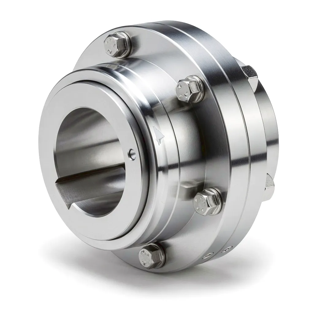
 Wind power has become the backbone of the United Kingdom’s ambition to reach net-zero carbon emissions. Stretching from the Scottish Highlands to the English Channel, Britain’s wind farms — both onshore and offshore — now contribute more electricity to the national grid than any other single renewable source. Behind every turbine that converts sea breeze or hillside gust into usable power sits a mechanical drivetrain engineered to an almost unforgiving specification. Vibration, shock loading, angular misalignment, and the relentless cycling between no-load and full-load conditions make the gearbox and its associated couplings the most mechanically demanding components in the entire machine. A gear type coupling, when specified correctly, absorbs these stresses without sacrifice to efficiency, alignment integrity, or service intervals — and that distinction matters enormously when a technician needs a vessel and a crane just to reach the gearbox.
Working Principle: How Gear Couplings Handle Wind Turbine Drivetrains
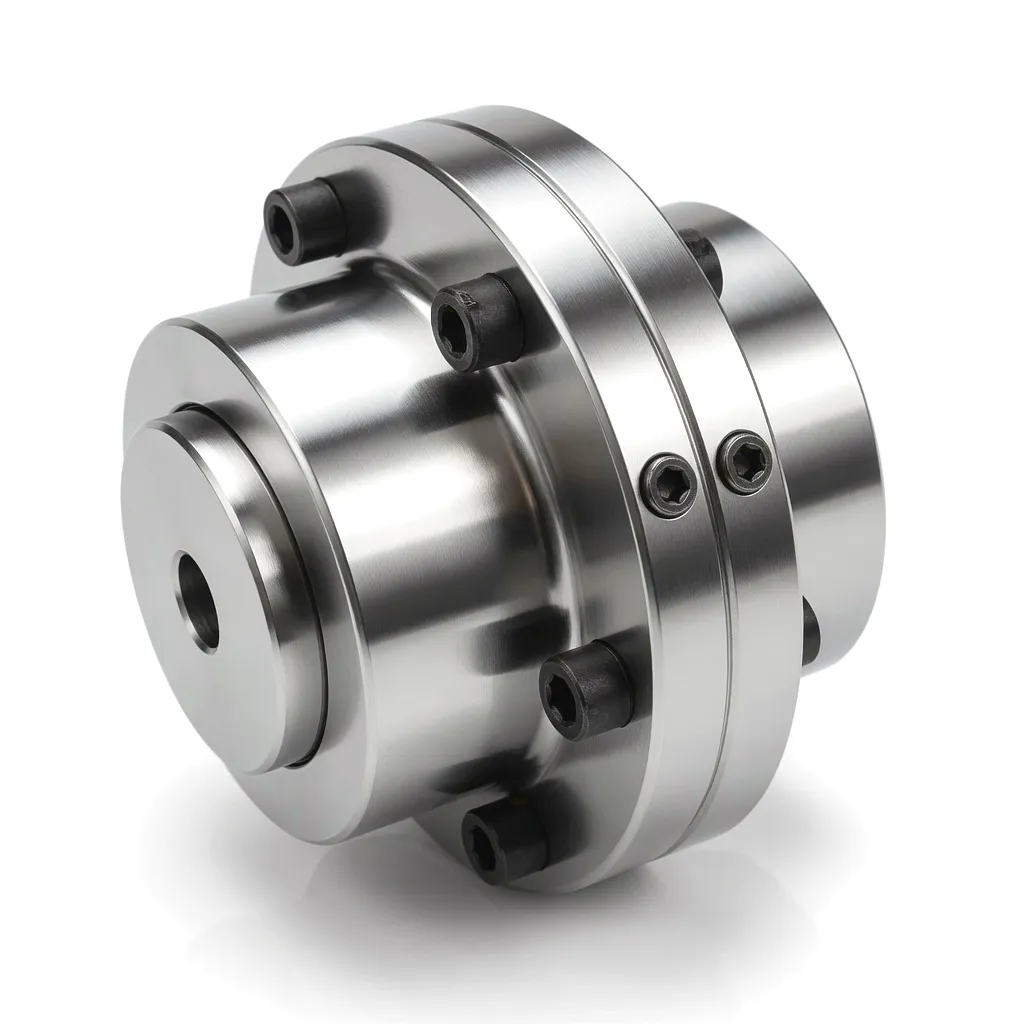
Crowned Tooth Mesh
The hub teeth are ground with a precise crown radius — typically 0.3 to 0.8 mm depending on bore size — which allows the sleeve and hub to tilt relative to one another without edge loading. In a wind turbine, rotor shaft deflection under asymmetric blade loading can reach 0.5° continuously; the crowned mesh accommodates this without inducing bending stress in the generator shaft, protecting both the generator bearing race and the coupling itself from fatigue failure.
Two-Piece Flanged Sleeve
A split flanged sleeve joined by high-tensile bolts allows assembly and disassembly without moving connected machinery along the shaft axis. On offshore turbines where access time is paid by the vessel hour, this design feature alone translates to real cost savings. The flanged split also provides a convenient inspection point: technicians can separate the sleeve halves to assess tooth wear without full dismantling during scheduled service visits in Bristol Channel or North Sea installations.
Sealed Grease Lubrication
Sealed lube chambers packed with high-viscosity, lithium-complex or polyurea grease rated for temperatures from -40 °C to +120 °C ensure continuous film lubrication even in the sub-zero conditions common to Scottish Highland sites in January. Grease nipples positioned at the pitch circle diameter allow in-situ re-greasing through the nacelle floor without turbine shutdown, preserving Annual Energy Production (AEP) figures that turbine operators report to National Grid ESO.
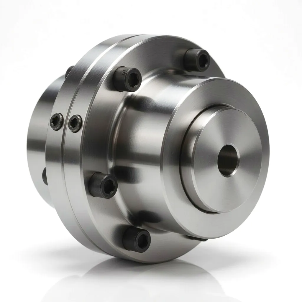 Material selection is not an afterthought in gear coupling specification — it directly governs torque density, fatigue life, and corrosion resistance. For wind turbine service in the United Kingdom’s coastal and highland environments, the metallurgical choices made at the manufacturing stage determine whether a coupling lasts three years or thirty.
Core Technical Advantages of Gear Type Couplings in Wind Power
Alta densidade de torque
Gear couplings deliver the highest torque-per-unit-diameter ratio of any flexible coupling type. A 250 mm pitch circle diameter gear coupling can transmit over 500 kNm, making it the only realistic coupling choice for multi-megawatt wind turbine low-speed shafts where both torque and space envelope are constrained by the nacelle’s structural steel cage.
Misalignment Tolerance
Angular misalignment accommodation of up to 1.5° per mesh (3° total in a double-engagement configuration) protects generator and main bearing from the bending moments generated by tower flexure and rotor mass imbalance. Parallel offset capacity up to 0.25 mm keeps the drivetrain forgiving even when turbine foundations experience seasonal settlement in the soft clay soils common to East Anglian and Lincolnshire wind farm sites.
Mechanical Efficiency >99.5%
Under properly lubricated conditions, gear coupling transmission efficiency typically exceeds 99.5% across the full torque range. For a 5 MW turbine operating 3,500 hours per year, the 0.5% efficiency delta over a rubber-element coupling recovers approximately 87,500 kWh annually — enough to power 30 average UK households and to meaningfully improve the project’s Levelised Cost of Energy (LCOE).
Shock Load Capacity
Gear couplings withstand short-duration shock torques of 2.5 to 3 times rated torque without permanent deformation. During wind gusts, grid-voltage dip events, or emergency brake engagement, this overload margin prevents coupling failure from propagating destructive torque spikes into the gearbox ring gear, which is far more expensive to replace than a coupling element and can take six months to source on the current UK supply chain.
20+ Year Design Life
When tooth contact stress is kept below 1,050 MPa (ISO 6336 Grade 5) and lubrication intervals are observed, gear couplings routinely reach 100,000 operating hours in wind turbine service. That aligns with the 20-year financial model on which most UK wind farm project finance is structured, and it removes coupling replacement from the O&M budget for the full concession period — a compelling argument at the business case stage.
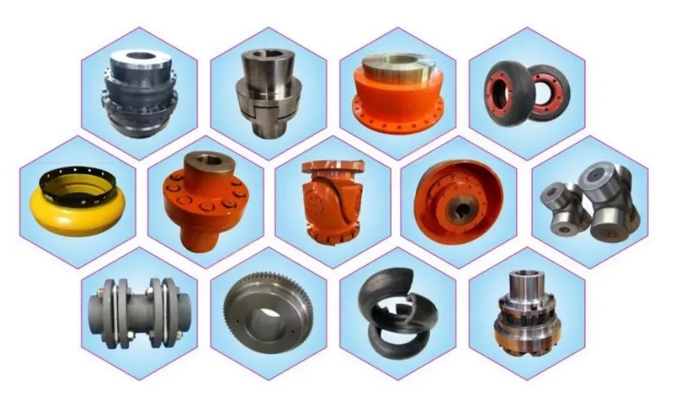
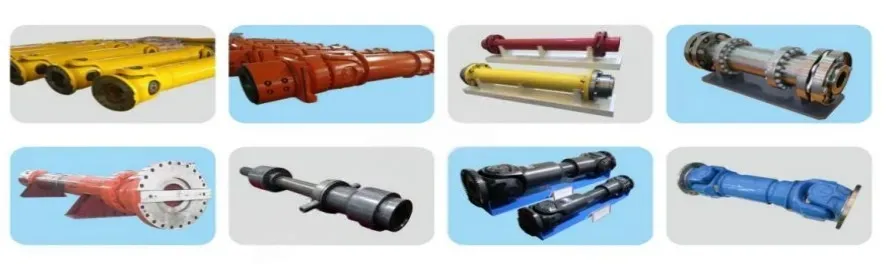
Product Technical & Performance Parameter Table
| Parâmetro | Small Series (GC-S) | Medium Series (GC-M) | Heavy Series (GC-H) | Wind Turbine Series (GC-WT) |
|---|---|---|---|---|
| Nominal Torque (kNm) | 0.5 – 25 | 25 – 150 | 150 – 600 | 200 – 2,500 |
| Desalinhamento angular máximo | 0.5° | 1.0° | 1,5° | 3.0° (double) |
| Deslocamento paralelo (mm) | 0.05 | 0.12 | 0.20 | 0.25 |
| Max Speed (RPM) | 5,000 | 3,500 | 2,000 | 1,800 |
| Material do Hub | C45 Steel | 42CrMo4 | 42CrMo4 Forged | 42CrMo4 / 20CrMnTi |
| Material da manga | Ductile Iron GGG50 | Ductile Iron ASTM A536 | Forged Steel / CF Composite | CF-Reinforced Forged Steel |
| Tooth Surface Hardness (HRC) | 55 – 58 | 58 – 60 | 58 – 62 | 60 – 62 |
| Operating Temperature (°C) | -20 a +80 | -30 a +100 | -40 a +120 | -40 a +120 |
| Lubrication Type | Grease / Oil Bath | Sealed Grease | Sealed Polyurea Grease | Long-Life Sealed Grease |
| Corrosion Protection | Phosphating | Zinc Plating | Zn-Ni + PTFE | Offshore Zn-Ni + PTFE (C5-M) |
| Design Life (hours) | 30,000 | 60,000 | 80,000 | 100,000+ |
| Compliance Standards | ISO 6336 | ISO 6336, BS 7608 | ISO 6336, DNV-ST-0361 | ISO 6336, DNV-ST-0361, IEC 61400 |
Wind Turbine Application Scenarios for Gear Type Couplings
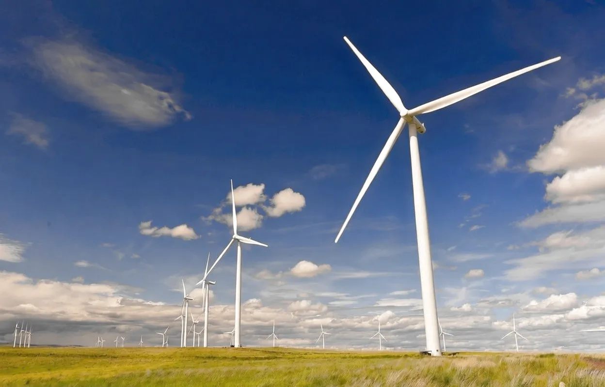
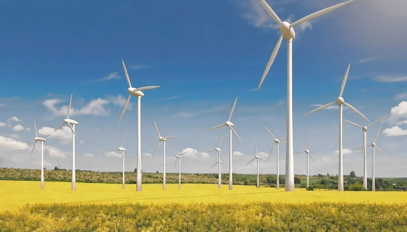
Across the United Kingdom’s wind energy landscape, gear couplings serve in several distinct drivetrain positions. Each location places unique mechanical demands on the coupling, and understanding those demands is key to selecting the right series and specification.

Manufacturing Excellence
Ever Power: Precision Gear Coupling Manufacturing & Customisation
Precision Machining Capability
Ever Power operates CNC hobbing and gear grinding centres capable of producing tooth profiles to ISO accuracy Grade 5 — a quality level that would previously have required European or Japanese sourcing. Tooth pitch deviation below 4 µm and profile slope error below 3 µm are routinely achieved across production batches, verified by Klingelnberg gear measurement centres with full CMM traceability. These tolerances are precisely what wind turbine OEMs specify for their certified drivetrain components, and they are what separates a coupling that lasts 20 years from one that reaches tooth wear limits in under five.
Full Custom Engineering Service
Ever Power’s engineering team works from customer-supplied load spectra, installation drawings, and environmental duty requirements to develop bespoke coupling designs. Bore configurations, keyway profiles, flange bolt-circle dimensions, spacer lengths, and surface treatment systems are all configurable without minimum-order constraints for turbine OEM qualification programmes. The team provides FEA-backed tooth contact analysis and ISO 6336 fatigue life calculations as part of the standard engineering package — documentation that supports DNV-ST-0361 type certification for wind components within the UK regulatory framework.
Reliable Supply Chain to the UK
Ever Power maintains bonded stock of high-runner gear coupling sizes in a European distribution hub, allowing 5–7 day delivery to UK addresses for standard series and 6–8 week lead times for full-custom designs. Shipping documentation conforms to UK customs tariff codes and CE/UKCA marking requirements, eliminating the administrative friction that delays project commissioning. Emergency ex-stock deliveries to port-based wind energy logistics centres in Hull, Hartlepool, and Dundee have been successfully completed within 72 hours of order placement — a service level that matters when an unplanned coupling failure threatens to take a turbine offline during a high-yield winter period.
Ready to discuss a bespoke gear coupling for your wind turbine project? Our engineering team responds within one business day.
Related Power Transmission Products
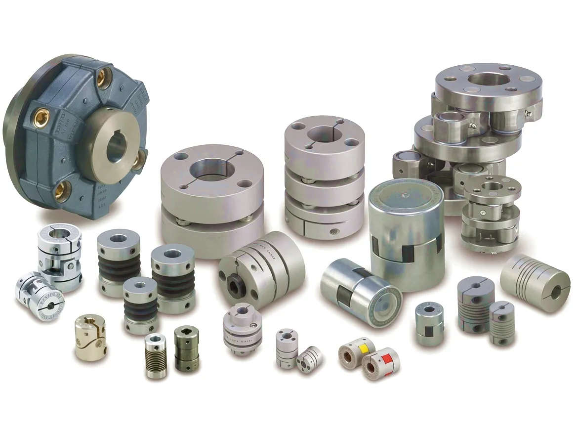
Wind turbine drivetrains rely on precise power take-off and gear management beyond the coupling itself. The following products from Ever Power complement gear coupling installations in wind energy and associated industrial machinery applications:
HC-RC31 PTO Gearbox
A robust power take-off gearbox designed for high-torque transmission in agricultural and industrial machinery. Its precision helical gearing and compact housing make it a natural pairing with gear couplings in applications requiring reliable, maintenance-friendly power transfer — including auxiliary drive systems on wind turbine maintenance equipment and field service vehicles.
HC-RC30-193 PTO Gearbox
The HC-RC30-193 combines a heavy-duty housing with a precisely configured gear ratio set, making it suitable for demanding power transmission applications where output torque consistency and input shaft flexibility are both required. When used alongside a correctly rated gear coupling, it forms a complete power transmission package capable of handling the variable torque profiles characteristic of wind-assisted equipment and renewable energy support machinery.
Customer Success Story: Humberside Offshore Wind — Hull, East Yorkshire
Project Overview
Hull, East Yorkshire — 2022 to Present
A wind turbine maintenance and retrofit contractor based in Hull — servicing turbines across the Humber Estuary and southern North Sea — approached Ever Power in 2022 with a chronic drivetrain reliability problem. A fleet of 44 turbines, originally commissioned in 2008, had been experiencing main-shaft coupling failures at an average rate of three per year. The original elastomeric disc-pack couplings were struggling to cope with the combination of high cyclic torque variance and salt spray ingress through worn nacelle seals, causing elastomer degradation and disc fatigue cracking within 24–30 months of each replacement. Unplanned downtime from coupling failures was costing the operator an estimated £380,000 per year in lost generation revenue and emergency vessel charter fees.
Ever Power Solution
Custom GC-WT Series Engineering
Ever Power’s engineering team conducted a full load spectrum analysis using ten-minute SCADA data supplied by the operator, deriving the actual torque distribution across 14 years of field operation. The analysis confirmed that peak torque events occurred 2.3 times more frequently than the original coupling design had assumed, due to changes in the control software made in 2015 that had increased turbine responsiveness to gust fronts. Ever Power designed a custom GC-WT 475 coupling — with a 475 mm sleeve bore, offshore Zn-Ni + PTFE coating, long-life polyurea grease fill, and a dedicated grease nipple accessible from the nacelle walkway — and supplied a pilot batch of eight units for field installation. Following 18 months of fault-free operation on the pilot turbines, the operator committed to a 44-turbine fleet retrofit delivered in three scheduled service campaigns across two winter seasons, co-ordinated to minimise grid curtailment during the critical Q4 and Q1 high-generation periods. The total project, from first coupling delivery to final turbine commissioning, was completed on time and within the agreed unit price — logistics coordinated through Hull’s King George Dock freight facility.
Outcome
In the 24 months following full fleet retrofit, coupling-related downtime events dropped to zero. Fleet availability improved from 91.4% to 96.8%, recovering approximately 1.2 GWh of additional annual generation across the 44 turbines. The operator estimated a payback period of 14 months on the coupling retrofit investment, and the savings continue to compound as each successive year passes without an emergency vessel call-out. The Hull-based maintenance team now uses Ever Power gear couplings as the standard specification across all future drivetrain overhauls in their Humber Estuary portfolio.
Customer Reviews
★★★★★
“We replaced the original elastomeric couplings on eight turbines with Ever Power’s GC-WT series in early 2023 and have had zero unplanned outages related to the drivetrain since. The tooth contact quality is visibly superior to what we removed — the crowned profile is machined to a precision you can feel during manual inspection. The offshore corrosion package has shown no signs of white rust at the 18-month inspection, which is frankly remarkable given the salt environment on the Humber. Ever Power’s lead time held exactly as promised, and their engineers were on the phone the moment we had any technical questions.”
— Operations Director, Wind Turbine Service Contractor, Hull
★★★★★
“The customisation service was what set Ever Power apart from the other suppliers we evaluated. They didn’t just offer a catalogue part and tell us to make it fit — they did a full torque spectrum analysis using our SCADA data and sized the coupling to our actual duty rather than a theoretical peak. The FEA report they provided was detailed enough to go directly into our DNV type extension documentation without revision. We specified custom grease nipple positions accessible from our walkway, and they delivered exactly that. Pricing was competitive even against commodity alternatives from the Far East.”
— Lead Mechanical Engineer, Offshore Wind O&M Provider, Grimsby
★★★★★
“We’ve been sourcing gear couplings for wind turbine test bench applications at our Sheffield facility for twelve years, and Ever Power’s GC-M series is the first product we’ve found that consistently meets our balance specification of G2.5 at 1,500 RPM without requiring additional correction at goods-in. The 25° pressure angle option they offer for our reversal-intensive test regimes was a genuine technical differentiator — no other supplier we contacted could accommodate that modification within a standard delivery window. Their quality documentation is thorough and traceable, which matters enormously when we’re validating results for turbine OEM customers.”
— Senior Test Engineer, Gearbox Validation Centre, Sheffield Advanced Manufacturing Park
Perguntas frequentes
Ready to Specify the Right Gear Coupling for Your Wind Turbine?
Talk to Ever Power’s engineering team. We cover the full specification process from load analysis to certified delivery — across the UK and offshore.
editado por gzl