
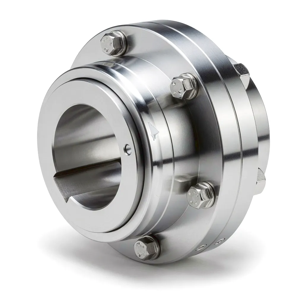
 Paper machines stand among the most mechanically demanding environments that any power transmission component can face. A modern Fourdrinier machine or tissue machine stretches well over a hundred metres from the wet end to the dry end, with each functional section — forming, pressing, drying, calendering, and reeling — driven through its own independent transmission arrangement. Within that arrangement, the gear type coupling is not a peripheral accessory. It is the critical mechanical link between motor, gearbox, and roll that keeps every part of the machine turning in synchronised harmony at the right torque and the right speed ratio. Get this link wrong, and a papermaking line that might represent an investment of tens of millions of pounds stops. Get it right, and the machine runs continuously, shift after shift, with minimal intervention from the maintenance team.
The challenge of selecting a coupling for paper machine service is not simply about rated torque. A gear coupling in this environment must simultaneously resist continuous moisture ingress — the forming section of a paper machine operates in near-saturated humidity with water spray everywhere — tolerate the misalignment that occurs as rolls expand thermally during warm-up, absorb the shock loads that occur whenever a paper break sends a sudden jolt through the drive train, and still maintain the precise speed ratio that prevents web tension from fluctuating and producing poor reel quality. That combination of requirements narrows the field considerably, and it explains why gear type couplings, with their involute tooth profiles, robust lubrication systems, and generous misalignment capacity, have become the default choice for drives rated above roughly 50 kW in serious paper production facilities across England, Scotland, and Wales.
How Gear Couplings Transmit Power Across Misaligned Shafts
Involute Tooth Mesh
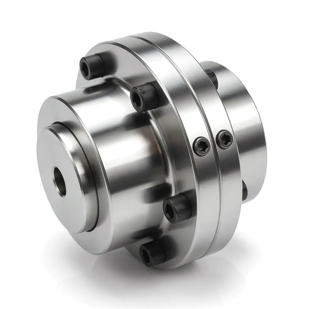
A gear type coupling consists of two hubs, each carrying external involute teeth, and an outer sleeve — sometimes called the gear ring or barrel — that carries matching internal teeth. Torque passes from the driving shaft through the hub teeth into the sleeve teeth and out through the opposite hub to the driven shaft. Because the tooth flanks are curved according to the involute function, the mesh can accommodate angular misalignment of up to around 1.5 degrees and parallel offset of several millimetres without generating significant secondary bending moments at the shaft ends. This is fundamentally different from a rigid coupling, where any misalignment is transferred directly as a bending load onto bearings and shafts, accelerating fatigue damage and bearing wear.
Smörjning och tätning
The gear mesh requires continuous lubrication to reduce wear and carry away frictional heat. In paper machine service, grease-lubricated variants with labyrinth seals and O-ring barriers are standard because the environment would contaminate oil-bath systems almost immediately. The grease is trapped between the sleeve and hub by a combination of centrifugal force and the seal geometry, forming a film that keeps tooth surfaces separated during operation. Re-greasing intervals are defined by the manufacturer and depend on operating speed, ambient temperature, and contamination level — in practice, a properly sealed gear coupling in paper machine service can run for three to six months between re-greasing events, which aligns conveniently with scheduled maintenance shutdowns.
Torque Path and Speed Ratio
Because the coupling transmits torque through a large number of simultaneously engaged tooth contacts rather than a single point of contact, the load is distributed across the full tooth width and the risk of localised overload is reduced significantly compared with jaw or pin-and-bush couplings. The coupling does not introduce any speed ratio change — input speed equals output speed — so it has no effect on the speed ratios established by the main gearbox. This is important in paper machine drives, where the speed ratio between adjacent sections must be maintained to very tight tolerances to control web tension. A gear coupling that introduced even a fraction of a percent of slip would cause unacceptable tension variation across the width of the web, resulting in breaks and product defects.
What Gear Couplings Are Made From — and Why It Matters
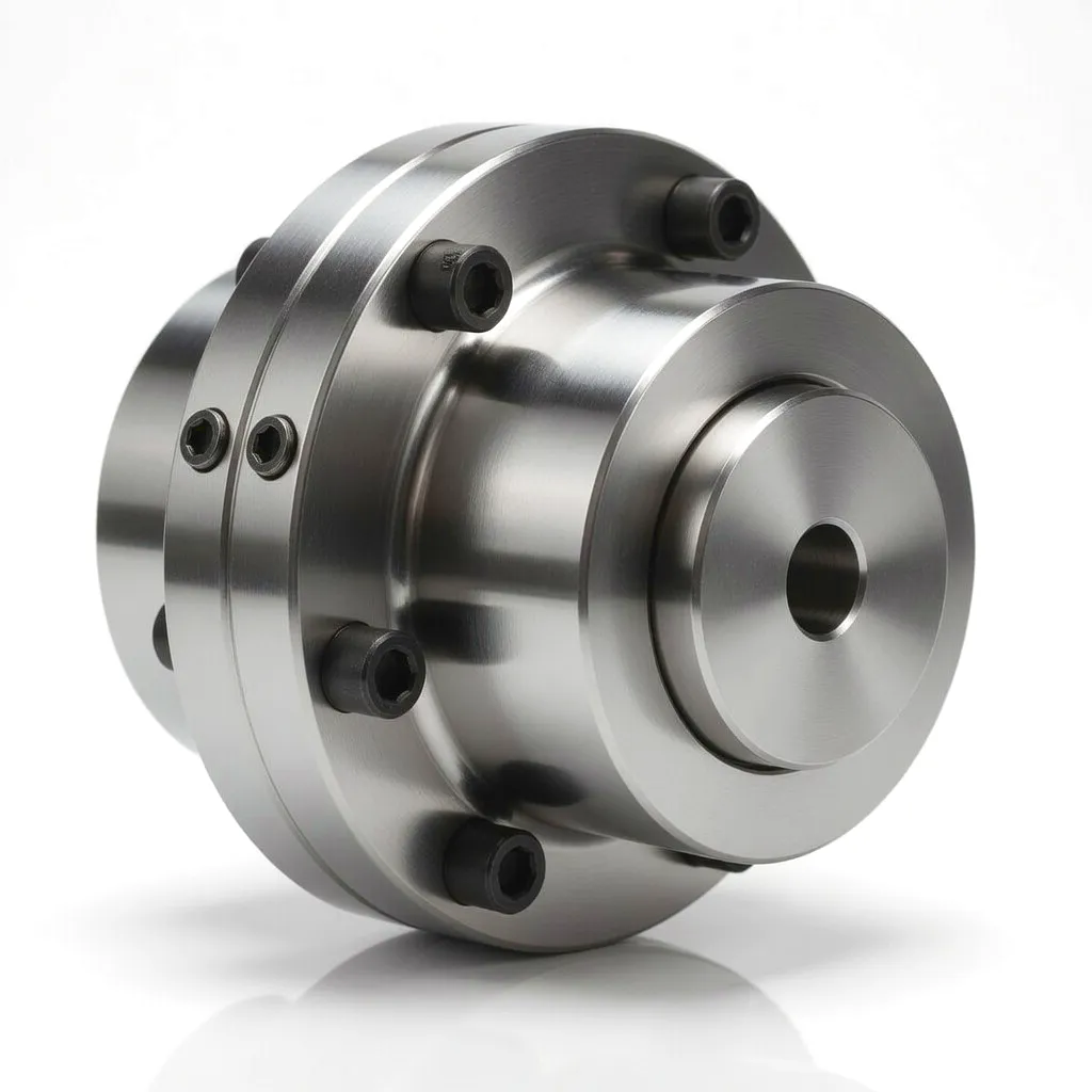 The choice of base material for a gear coupling hub has a direct effect on rated torque, corrosion resistance, weight, and cost. In the vast majority of paper machine applications, hubs are machined from medium carbon steel — typically 45 steel or its British equivalent EN 8 — and then subjected to heat treatment to achieve a surface hardness of 50 to 58 HRC on the tooth flanks. This combination of a tough core with a hard surface gives the coupling excellent resistance to both shock loading and tooth wear. The sleeve, which sees smaller contact stresses because its internal teeth engage across a larger pitch circle, is commonly manufactured from the same grade or from a slightly lower-carbon alloy, making it marginally more ductile so that it acts as the sacrificial element in an overload event, protecting the more expensive shafts and gearboxes.
In applications where the coupling is exposed to chemical pulp, bleaching compounds, or anti-foaming agents — conditions encountered in integrated pulp-and-paper mills found in Scotland and the north of England — stainless steel grades such as 316L are specified for external surfaces and fasteners, while the load-bearing tooth geometry is retained in alloy steel with appropriate coating or plating for corrosion protection. Zinc-phosphate treatment followed by epoxy primer is a common approach in UK facilities that must meet environmental regulations on runoff from maintenance areas. For the highest-speed applications, such as the pope reel drive at the dry end of a tissue machine where peripheral velocities at the coupling pitch circle may reach 10 m/s or more, the hub and sleeve assembly is precision balanced after final machining to a grade consistent with ISO 1940 G2.5, ensuring that residual unbalance does not generate vibration at running frequency and its harmonics.
Navmaterial
45 / EN8 carbon steel, heat-treated; 316L stainless for corrosive environments
Sleeve / Barrel
Alloy or ductile iron; steel with epoxy primer for high-moisture zones
Seals & Fasteners
Nitrile or Viton O-rings; A4-grade stainless fasteners where chemical splash risk exists
Ytbehandling
Zinc phosphate + epoxy primer; optional zinc-nickel plating for offshore-grade corrosion resistance
Six Reasons Gear Couplings Outperform Alternatives in Paper Machine Drives
High Torque-to-Weight Ratio
Gear couplings transmit torque through multiple tooth contacts simultaneously, delivering rated torques that would require a much larger jaw coupling or disc coupling to match. This compact power density is valued in paper machine drives where space between adjacent rolls is limited and the drive arrangement must fit within the machine’s structural envelope.
Angular and Parallel Misalignment Tolerance
Paper machine rolls change diameter as the paper web builds on reels, and the structural framework of the machine undergoes thermal expansion during warm-up from cold. These effects create real-world misalignment that must be accommodated without transferring destructive side loads to the roll bearings. Gear couplings handle angular misalignment up to approximately 1.5° and parallel offset up to 1 mm per 100 mm of coupling length, offering much greater tolerance than rigid flanged couplings.
Shock Load Absorption
When a paper web breaks at the press section, the sudden release of tension sends a torque impulse back through the drive train that can be several times the rated operating torque. Gear couplings, particularly those designed with crowned tooth profiles, distribute this impulse across all engaged teeth and allow a degree of angular rocking that absorbs peak energy before it reaches the gearbox or motor. This characteristic significantly reduces the frequency of gearbox damage attributable to paper break events.
Long Service Life with Predictable Wear
Properly lubricated and aligned gear couplings routinely achieve service lives of 30,000 hours or more in paper machine duty. Wear patterns on gear teeth are easy to assess during planned maintenance shutdowns using standard go/no-go gauges, giving maintenance engineers a clear decision point for replacement rather than relying on condition monitoring alone. This predictability supports the planned maintenance cycles that are standard in UK paper production facilities.
High Operating Speed Capability
When balanced to ISO 1940 G2.5 or better, gear couplings can operate at pitch line velocities exceeding 20 m/s without generating unacceptable vibration. This makes them suitable for use on the high-speed sections of modern tissue machines and fine-paper machines running at wire speeds above 1,800 m/min — performance levels that would rapidly overheat or mechanically fail most elastomeric coupling designs.
Repairability and Interchangeability
Unlike bonded elastomeric couplings or laminated disc packs, a worn gear coupling can often be repaired by replacing the sleeve alone while retaining the original hubs, reducing both parts cost and shaft re-machining work. Standardisation to ISO or DIN dimensional series also means that hubs from multiple suppliers can often be combined with a replacement sleeve in an emergency, a practical benefit that plant engineers in Birmingham, Leeds, and other manufacturing centres have relied upon to minimise unplanned downtime.
Gear Type Coupling — Key Performance Parameters
| Parameter | Typiskt intervall | Notes |
|---|---|---|
| Nominellt vridmoment | 100 Nm – 2,500,000 Nm | Subject to series and module selection |
| Maximal driftshastighet | Up to 6,500 rpm | Balanced to ISO 1940 G2.5 at high speeds |
| Vinkelförskjutningskapacitet | Upp till 1,5° | Per coupling element; crowned tooth profile |
| Parallell offsetkapacitet | Up to 1 mm per 100 mm | Depends on bore diameter and tooth geometry |
| Hub Bore Diameter Range | 20 mm – 520 mm | Keyway, spline, or interference fit options |
| Peak (Momentary) Torque | 2.5× rated torque | Standard service factor; higher on request |
| Driftstemperaturområde | -30 °C to +150 °C | Dependent on grease specification; Viton seals extend upper limit |
| Tooth Profile Standard | Involute (crowned); 20° pressure angle | DIN 740 / ISO 14691 compliant |
| Hub Surface Hardness | 50 – 58 HRC | Induction hardened tooth flanks |
| Balance Grade | ISO 1940 G6.3 standard; G2.5 on request | G2.5 required for speeds above 3,000 rpm |
| Protection Rating | IP55 standard; IP65 with enhanced sealing | Critical for wet end and press section service |
Six Critical Drive Positions Where Gear Couplings Deliver in Paper Machine Operation
Each section of a paper machine presents a distinct engineering challenge. The following scenarios reflect real operating conditions encountered at integrated mills and converting facilities throughout England, Scotland, and Wales.
Application Scenario 1: Wet End Forming Section — Breast Roll and Table Roll Drives
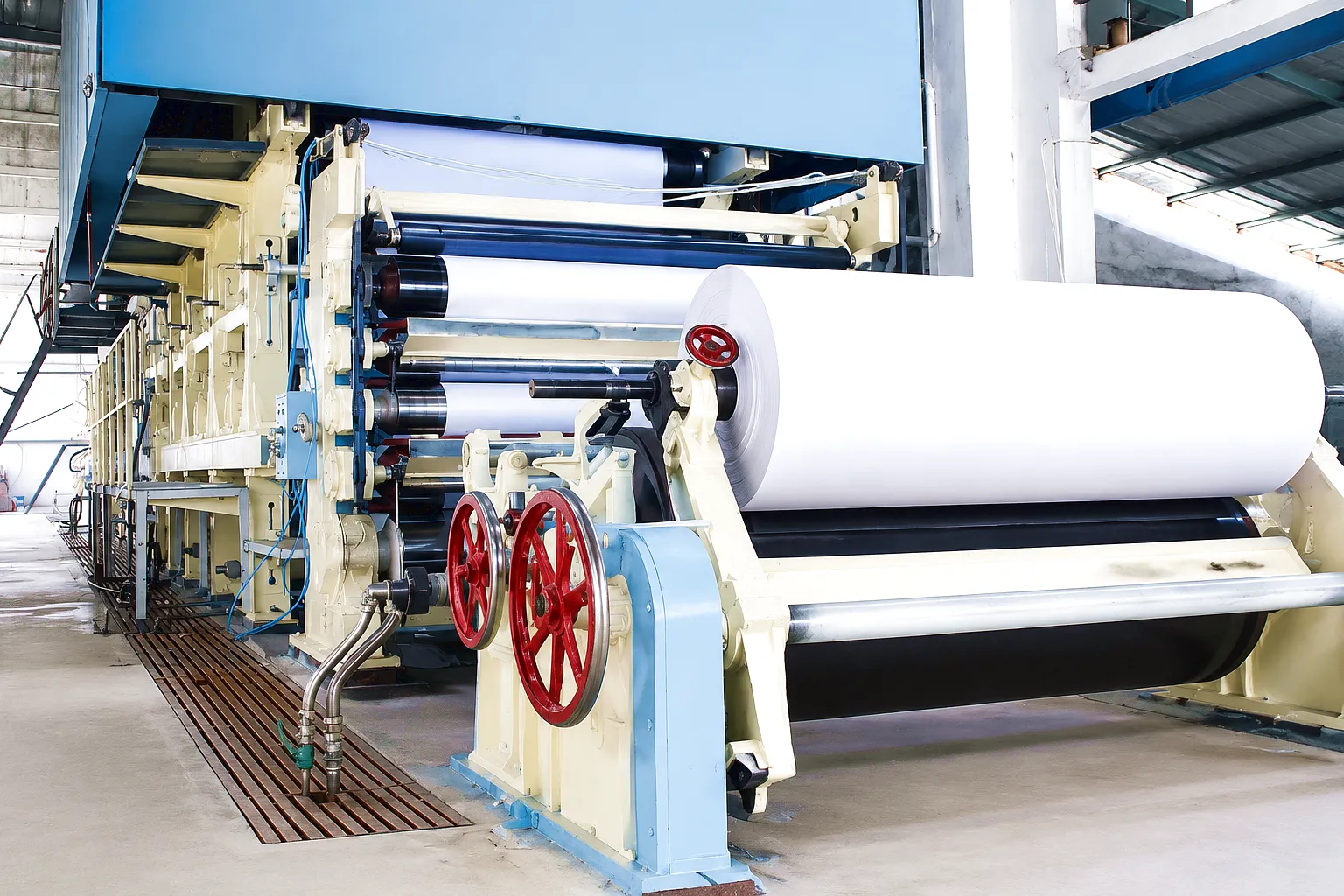
The forming section is where paper stock — a suspension of fibres in water at roughly 99% water content — is delivered onto the moving forming wire. Every table roll, foil blade, and suction box has to be driven through the same waterlogged atmosphere. Gear couplings used here face the harshest moisture conditions on the machine. The breast roll drive in particular operates at low speed but very high torque, drawing the wire across the full machine width against the resistance of water drainage. Couplings at this position are specified with IP65-rated labyrinth seals and high-viscosity grease because water laden with fine fibres and fillers will penetrate any inadequate seal arrangement within days. The consequences of a coupling failure at the wet end are severe: a broken wire or a stopped breast roll during production can take eight to twelve hours to recover, representing lost output that smaller UK paper mills — particularly those operating tissue and board lines in the Midlands — simply cannot afford. A gear coupling rated conservatively at 2.5 times the calculated operating torque, with a stainless-steel sleeve, provides the reliability margin that maintenance managers need to sign off on a 12-month re-inspection interval.
Application Scenario 2: Press Section — Felt Press Roll Drives Under Nip Loading
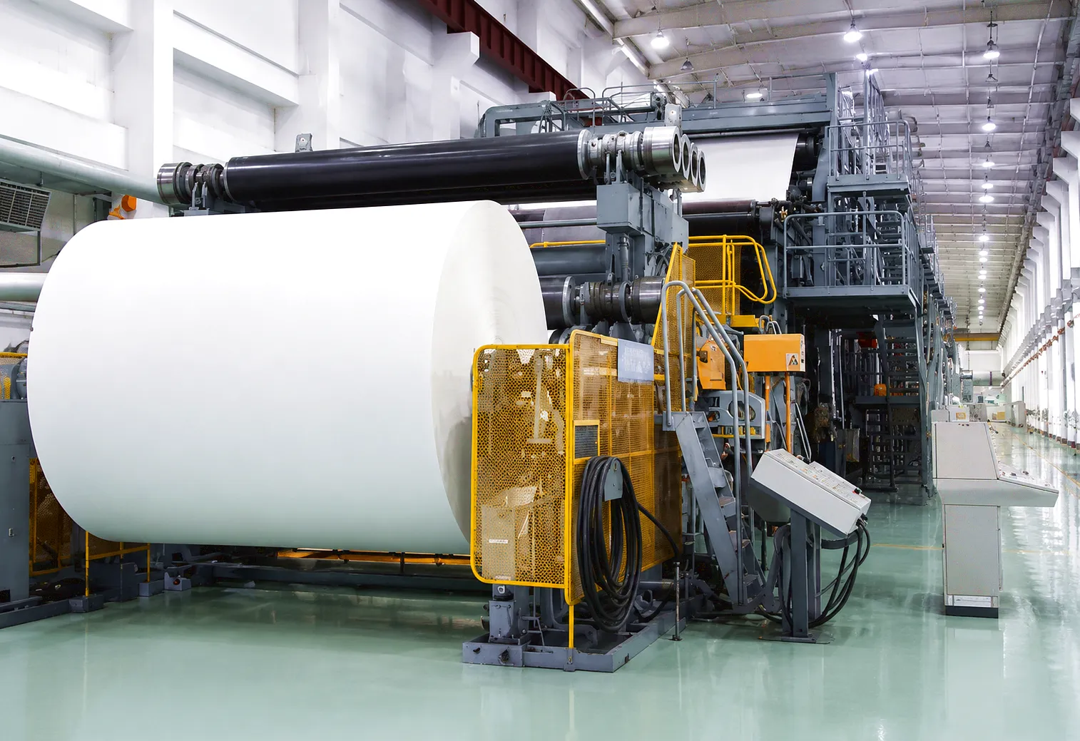
The press section removes water from the wet paper web by passing it through one or more roll nips under pressures that can exceed 900 kN/m of nip width. The felt rolls that carry the web through the press nips are driven through gear couplings that must simultaneously handle continuous torque from the main drive, accommodate shaft deflection caused by nip loading — which creates a measurable angular misalignment at the coupling — and resist the combination of warm water, felt wash spray, and fine paper fibres that characterises the press section atmosphere. Central to correct coupling selection here is the crowning geometry of the gear teeth: a badly crowned tooth will create edge loading when the shaft deflects under nip load, accelerating surface fatigue and leading to premature flaking of the tooth flanks. Ever Power’s press-section coupling range uses a computer-optimised crown radius that maintains full tooth contact under angular misalignment conditions up to 0.8°, providing a safety margin over the typical shaft deflection angle at press section nip loads. Major integrated mills operating in Sheffield and Nottingham have adopted this specification for their press section rebuilds precisely because they can demonstrate reduced tooth wear between planned overhauls.
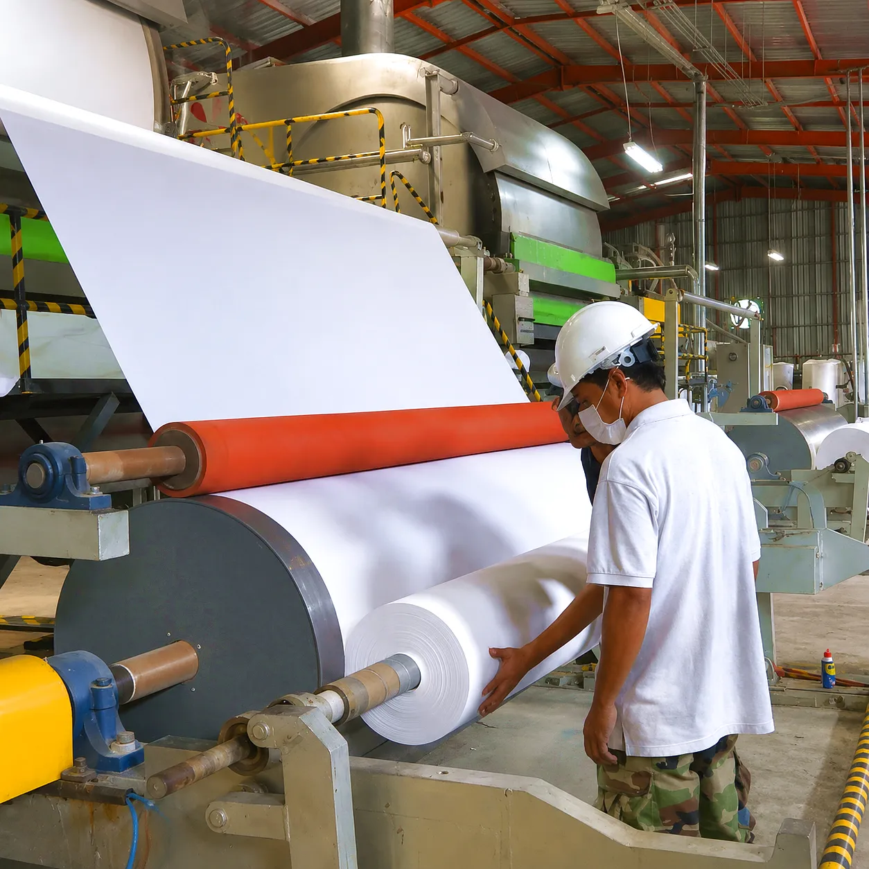
Application Scenario 3: Dryer Section — Multi-Cylinder Steam-Heated Drive with Speed Draw Control
A typical multi-cylinder dryer section on a graphic paper machine contains between 40 and 80 drying cylinders arranged in two tiers, each cylinder heated internally with steam at temperatures between 100 °C and 160 °C. The cylinders are grouped into drive sections — typically four to eight cylinders per group — connected through a common overhead gear drive, with each group running at a slightly higher speed than the previous one to maintain a controlled draw ratio that prevents the paper web from slackening and causing wrinkles. The gear couplings connecting each cylinder shaft to its drive gear must therefore operate at elevated temperature, in an environment of steam and condensate, and at shaft diameters that can exceed 200 mm on wide-web machines. Thermal growth of the cylinder shell between cold start and operating temperature shifts the shaft position by several millimetres, generating angular misalignment at the coupling that must be absorbed without increasing the resistance torque seen by the drive motor. In the dryer section of large machines found in board mills in the North West of England, a single coupling failure can require partial dismantling of the cylinder group, making mean time between failures a critical procurement criterion and justifying a higher specification coupling even at premium cost.
Application Scenario 4: Calender Stack — High-Speed Precision Drive for Surface Quality Control
The calender stack smooths the paper surface by passing it through a series of roll nips at high speed and controlled nip load. On a machine producing coated graphic paper at 1,200 m/min or above, the calender rolls rotate at several hundred rpm and any rotational irregularity at the coupling — caused by eccentric mass, tooth spacing error, or inadequate lubrication — produces a periodic variation in nip pressure that prints a banding pattern onto the paper surface. This surface defect, known in the trade as barring or calender barring, is one of the most difficult quality problems to diagnose and eliminate. Gear couplings selected for calender service must therefore meet tighter manufacturing tolerances on tooth spacing and runout than equivalent couplings for lower-speed drive positions. Specifically, tooth spacing error should not exceed 5 microns on gear couplings intended for calender service, and balancing should be performed with the coupling assembled on a mandrel representing the actual shaft rather than an arbitrary stub. UK paper producers supplying quality-sensitive print markets — including several facilities in the South East and in Merseyside — have moved in recent years toward pre-selected, individually certified calender couplings supplied with inspection records, rather than selecting from general stock, to give their quality management systems the documented traceability that modern print contracts demand.
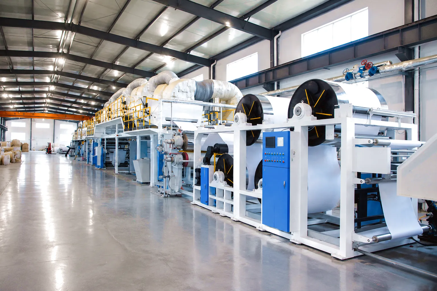
Application Scenario 5: Pope Reel and Winder — Variable Torque Drive During Roll Building
At the dry end of the machine, the paper web is wound onto a parent reel, known in the UK trade as a pope reel, at full machine speed. As the reel builds in diameter, the torque required to maintain constant web tension decreases, but the rotational inertia of the reel increases dramatically — a full parent reel on a board machine may weigh 40 tonnes or more. The drive coupling at the pope reel spool must therefore handle the very high peak torque during initial core pickup, when the machine motor accelerates the empty spool from rest to full wire speed in a matter of seconds, as well as the lower steady-state torque during reel building and the sudden torque reversal that occurs when the reel is cut and the drive transfers to a new empty spool. This cycling duty, repeated multiple times per shift on a tissue machine, generates fatigue loading on coupling teeth that accumulates over the service period. Gear couplings for winder service are therefore specified with a higher service factor — typically 2.0 to 3.0 — and may be designed with a higher tooth module than the rated torque alone would require, providing additional root bending strength to resist the fatigue cycles that characterise winding duty.
Application Scenario 6: Headbox Fan Pump — High-Speed, High-Flow Hydraulic Drive
The fan pump circulates the paper stock from the machine chest to the headbox at controlled pressure and flow rate, ensuring that the jet velocity issuing from the headbox slice lip precisely matches the forming wire speed for the paper quality being produced. Fan pumps on wide, high-speed paper machines are typically driven by motors rated between 200 kW and 2,000 kW, with the motor and pump connected through a direct or geared drive arrangement in which gear couplings appear at both the motor output and pump input. Pump drives are characterised by continuous duty at rated torque with low shock loading, but the speeds are high — fan pump drives may run at 1,500 rpm to 3,000 rpm — and the consequences of coupling failure are severe because a fan pump trip will cause an immediate change in headbox jet velocity, producing a grammage streak across the full width of the paper web that contaminates the production reel. UK paper mills managing tight quality specifications for newsprint and publication-grade papers have found that upgrading fan pump couplings to a higher-precision gear specification — with certified tooth profile inspection — is one of the most cost-effective quality assurance investments available without major capital expenditure.
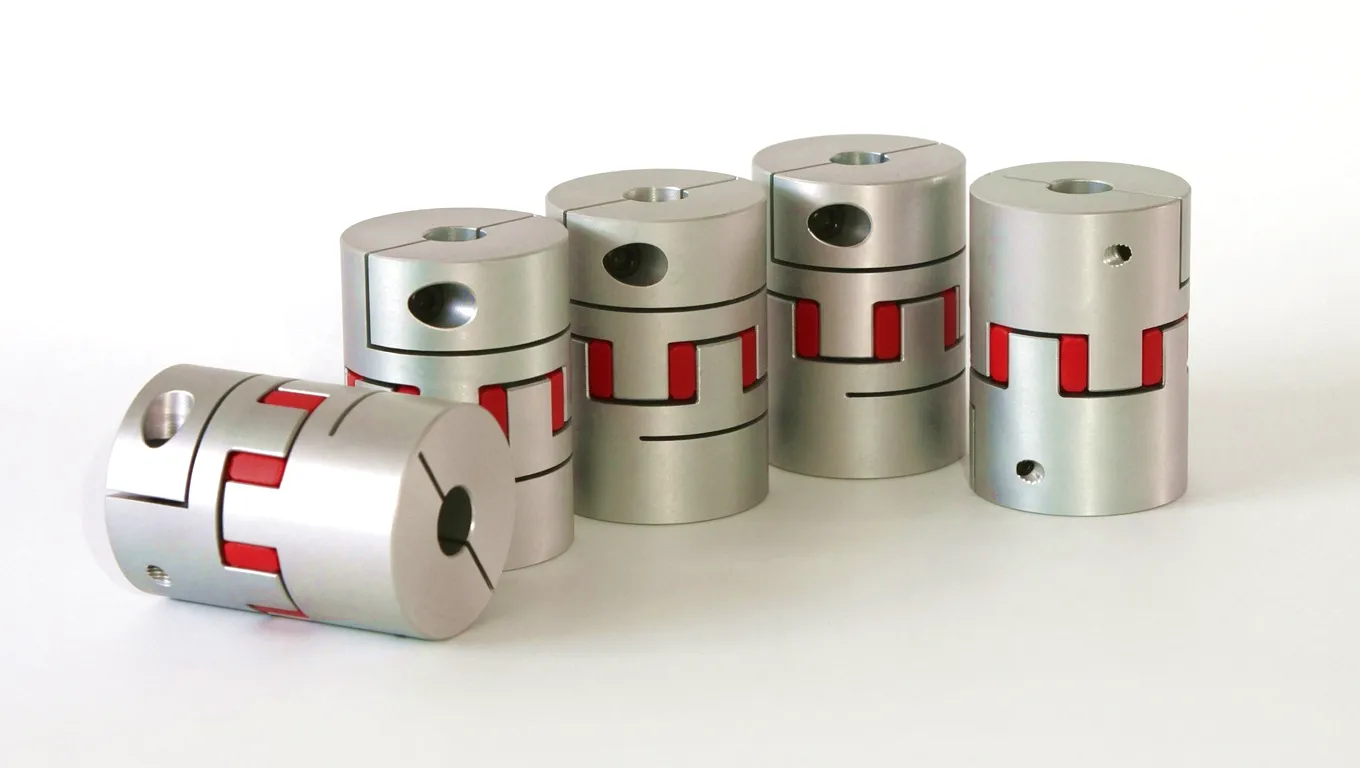
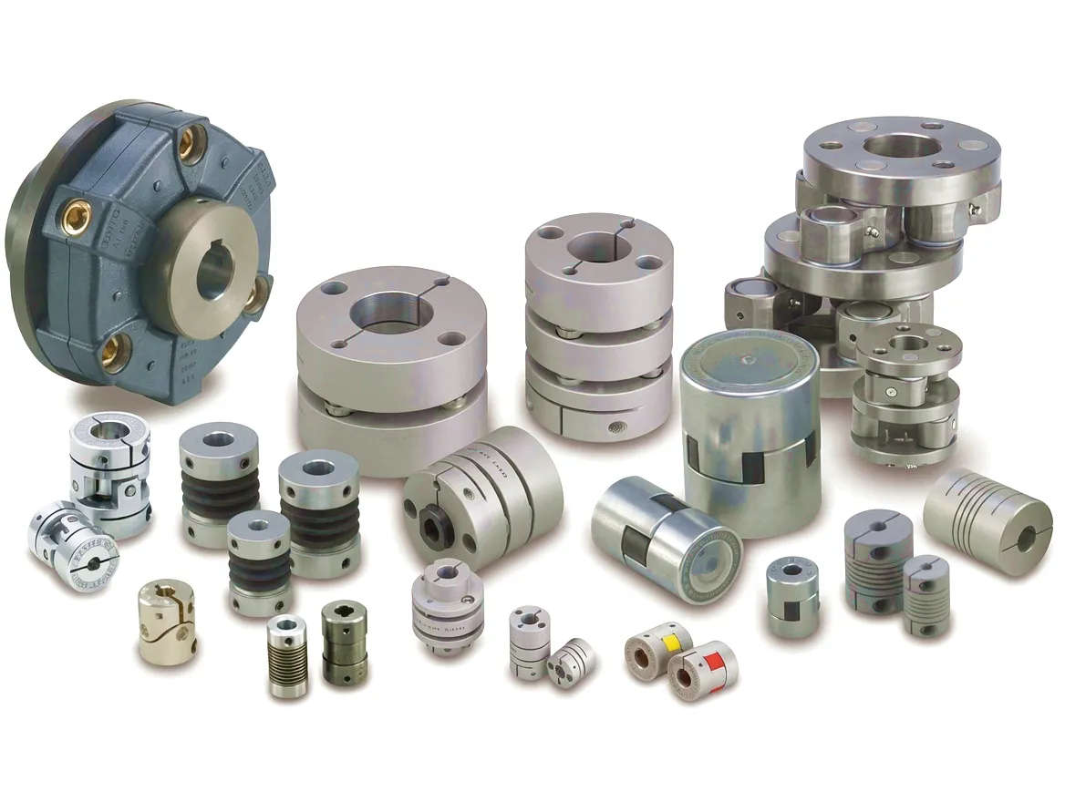
Ever Power Gear Type Coupling Product Range
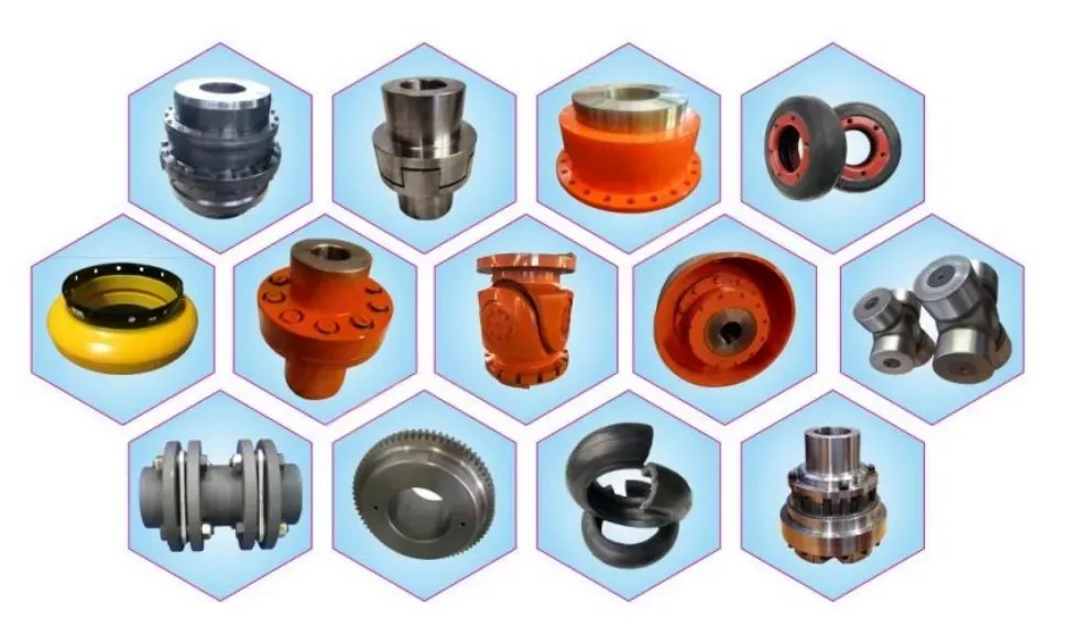
Complementary Drive Solutions from Ever Power
HC-RC31 PTO Gearbox
The HC-RC31 is a right-angle PTO gearbox designed for demanding continuous-duty agricultural and industrial power take-off applications. Its compact, robust housing integrates seamlessly with gear type coupling hubs at the output flange, making it an efficient pairing for equipment requiring both right-angle drive direction change and the misalignment tolerance that only a gear coupling arrangement can provide. UK customers sourcing integrated gearbox-and-coupling assemblies for purpose-built industrial machinery will find the HC-RC31 a cost-effective foundation for custom drive trains.
HC-RC30-193 PTO Gearbox
The HC-RC30-193 offers a higher-ratio output configuration suited to applications requiring significant speed reduction at the PTO interface, such as fan pumps, agitators, and slow-speed roll drives. When combined with a gear type coupling at the driven machine input, the full drivetrain delivers precise speed control, good misalignment tolerance, and the torque multiplication that simplifies motor sizing for larger industrial installations. This gearbox is available with custom output flanges to match existing plant shaft standards across UK manufacturing facilities.
How a Sheffield Board Mill Eliminated Press Section Downtime with Ever Power Gear Couplings
 A medium-format board mill operating two Fourdrinier lines in Sheffield had been experiencing recurring unplanned shutdowns on the press section of its Number 2 machine, averaging 4.2 hours of lost production per month over an 18-month period. Maintenance analysis attributed the stoppages to accelerated wear of the press roll drive couplings, which were failing at tooth flanks within 8,000 to 9,000 operating hours — well below the 25,000-hour target life that the maintenance manager had established as the benchmark for the section.
Root cause investigation conducted jointly with the Ever Power applications team identified two contributing factors. The original couplings had been selected without accounting for the angular misalignment that developed when the centre-press roll heated and expanded under normal production conditions; the resulting edge loading was consuming the tooth crowning allowance within the first 3,000 hours of service. In addition, the grease type originally specified for the application degraded rapidly in the combination of elevated temperature and water vapour present in the press section atmosphere, leading to boundary lubrication conditions and accelerated surface fatigue.
Ever Power supplied a set of replacement gear couplings with a revised crowning geometry calculated from the measured shaft deflection data provided by the mill, together with a high-temperature, water-resistant grease formulation and an extended-length labyrinth seal that doubled the grease retention volume. The new couplings were installed during a scheduled six-day maintenance shutdown. In the 24 months following installation, the Number 2 press section recorded zero unplanned coupling-related stoppages. The maintenance team estimated the avoided downtime cost at over £340,000, against a total procurement cost for the Ever Power coupling set of approximately £18,500 — a return on investment that justified upgrading the Number 1 machine to the same specification at its next planned overhaul.
What Our UK Customers Say
“The revised crowning geometry that Ever Power’s engineers calculated for our press section rolls made an immediate difference. We went from fighting coupling wear every quarter to a completely predictable 12-month inspection regime. The quality of the inspection documentation they supply also satisfies our ISO 9001 auditors without any additional work on our end.”
— Plant Maintenance Manager, Board Mill, Sheffield
“We specified bespoke bore diameters and a split-sleeve arrangement for in-situ installation on our dryer section — something our previous supplier refused to quote on. Ever Power turned around certified drawings within five working days and delivered the finished couplings in six weeks. The fit on our press rolls was exact. No rework, no adjustment needed on site.”
— Drive Systems Engineer, Tissue Mill, Manchester
“Price is always a consideration but what closed the deal for us was the dynamic balance certificate and the application support. When we told Ever Power our calender machine speed and the quality spec we were producing, they came back with a specific recommendation and the test data to support it. That level of technical engagement from a supplier is rare and genuinely useful in a production environment where you cannot afford to get the coupling selection wrong.”
— Senior Mechanical Engineer, Graphic Paper Mill, Leeds
Common Questions from UK Paper Industry Drive Engineers
Ready to Specify the Right Gear Coupling for Your Paper Machine?
Send your shaft drawings and operating data to the Ever Power technical team for a fast, application-specific quotation — no obligation, response within 48 hours.
redigerad av gzl