
 Cement manufacturing is one of the most energy-intensive industrial processes on the planet, and the grinding circuit sits at its very heart. A single cement mill in a modern UK plant — whether located in the limestone-rich Midlands, the quarry belts of Yorkshire, or the industrial corridors around Rugby — can consume upwards of several megawatts of electrical power around the clock. Within that system, the coupling connecting the primary drive motor to the reduction gearbox is far more than a mechanical link. It is the load-sharing, shock-absorbing, misalignment-tolerating backbone of the entire drive train. When that component fails, the cost is not just the coupling itself — it is the unplanned downtime, the missed kiln throughput target, the emergency engineering call-out, and the contractual penalties that ripple outward through the supply chain.
The UK cement sector operates under exceptional pressure. Environmental compliance requirements from the Environment Agency, combined with tightening energy efficiency targets under the UK’s Industrial Decarbonisation Strategy, mean plant engineers must extract every possible hour of uptime from their assets. In this context, coupling selection is a genuine engineering discipline, not a commodity purchasing decision. The right gear coupling, snake spring coupling or universal joint coupling, specified correctly for start-up torque multiples, ambient dust ingress levels, and thermal expansion characteristics, can quietly deliver five or more years of uninterrupted service. The wrong one, or a poorly maintained correct one, becomes the single-point failure in a multi-million-pound production asset.
How Couplings Function Inside a Cement Mill Drive Train
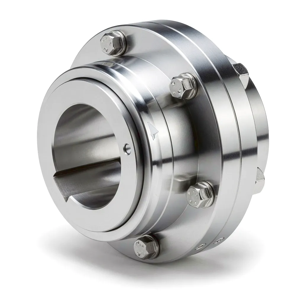
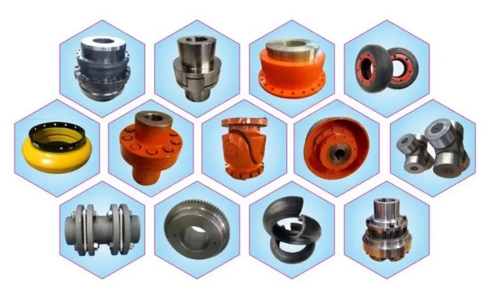
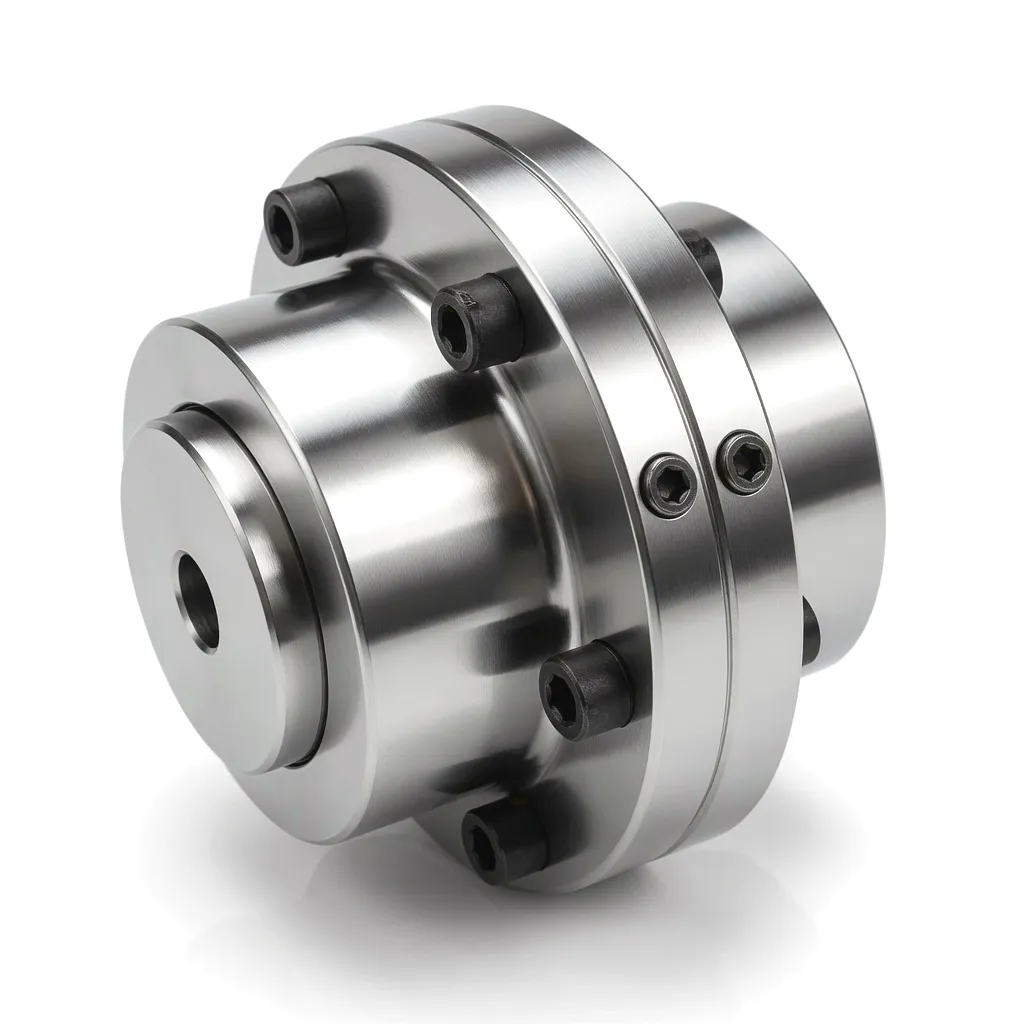
At the mechanical core of every cement mill drive is the coupling assembly, and understanding how it functions under real operating conditions is essential before any selection decision is made. A gear-type coupling, the most widely deployed variant in high-power cement mill drives, operates on the principle of crowned-tooth engagement. The external gear hub, machined to a tight tolerance profile, mates with an internally toothed sleeve. The crowned-tooth geometry — a slight convex curvature on each tooth flank — allows the hub and sleeve to articulate through angular misalignment of up to 1.5 degrees while continuing to transmit full rated torque. This self-compensating geometry is the reason gear couplings have remained the preferred solution for multi-megawatt drive trains for over half a century.
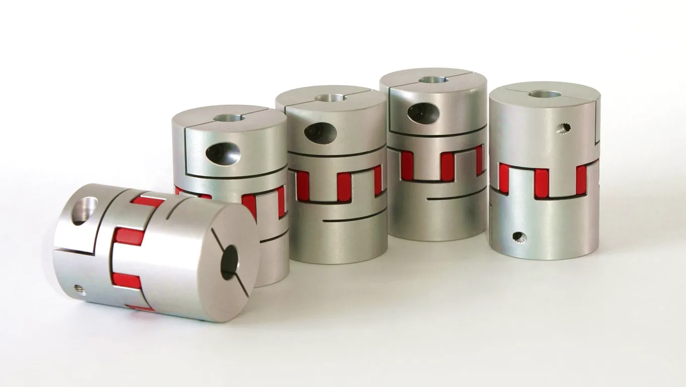
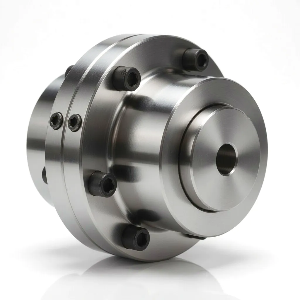 Snake spring couplings operate on a distinct mechanical principle that makes them particularly well-suited to drive systems where vibration isolation and torsional compliance are the priority. Rather than transmitting torque through meshing teeth, the snake spring coupling uses a continuous sinusoidal spring element — the “snake” — that is threaded through interlocking flanges on each coupling half. As torque is applied, the spring element deflects, absorbing torsional shock before it reaches the downstream components. This spring-damping mechanism is highly effective at attenuating the torsional vibration peaks that occur when a large induction motor is switched on and the rotor windings are energised against a stationary, fully loaded mill barrel. The spring constant can be tuned during manufacture by varying the cross-sectional profile, material grade, or coil geometry of the spring element, giving design engineers a powerful means of matching coupling stiffness to the resonant frequency profile of the complete drive system.
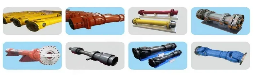
Universal couplings — often referred to in the UK as cardan joints or Hooke’s joints in legacy plant documentation — handle higher angular offsets than gear couplings, typically up to 15 to 25 degrees depending on the series and the operating speed. In cement plant drive trains, universal couplings tend to appear in auxiliary drive arrangements rather than in the primary high-power mill drive, specifically in applications such as driving the cement mill’s auxiliary turning gear, the skip hoist drive on raw material handling systems, or in the output shaft arrangements of vertical roller mill gearboxes where shaft alignment is constrained by available headroom. The double-cardan variant, which incorporates two cross joints with a centring mechanism, achieves near-constant velocity output, eliminating the second-order velocity oscillation that is inherent to a single Hooke’s joint operating at angle. This characteristic makes double-cardan couplings highly desirable in applications where smooth torque delivery at the driven shaft is critical to product quality or equipment fatigue life.
Core Manufacturing Materials in Industrial Couplings
The material selection for coupling components in a cement mill environment is not simply a matter of mechanical strength. Engineers must also account for operating temperature ranges, the abrasive and corrosive nature of the cement dust atmosphere, the consequences of thermal expansion mismatch between hub bore and shaft, and the absolute necessity of maintaining dimensional integrity over a maintenance interval that may stretch to eighteen months or more. The following breakdown reflects the material decisions that tier-one coupling manufacturers and UK plant engineering teams actually make on the ground.
Application Scenario: Cement Mill Drive Systems in UK Plants
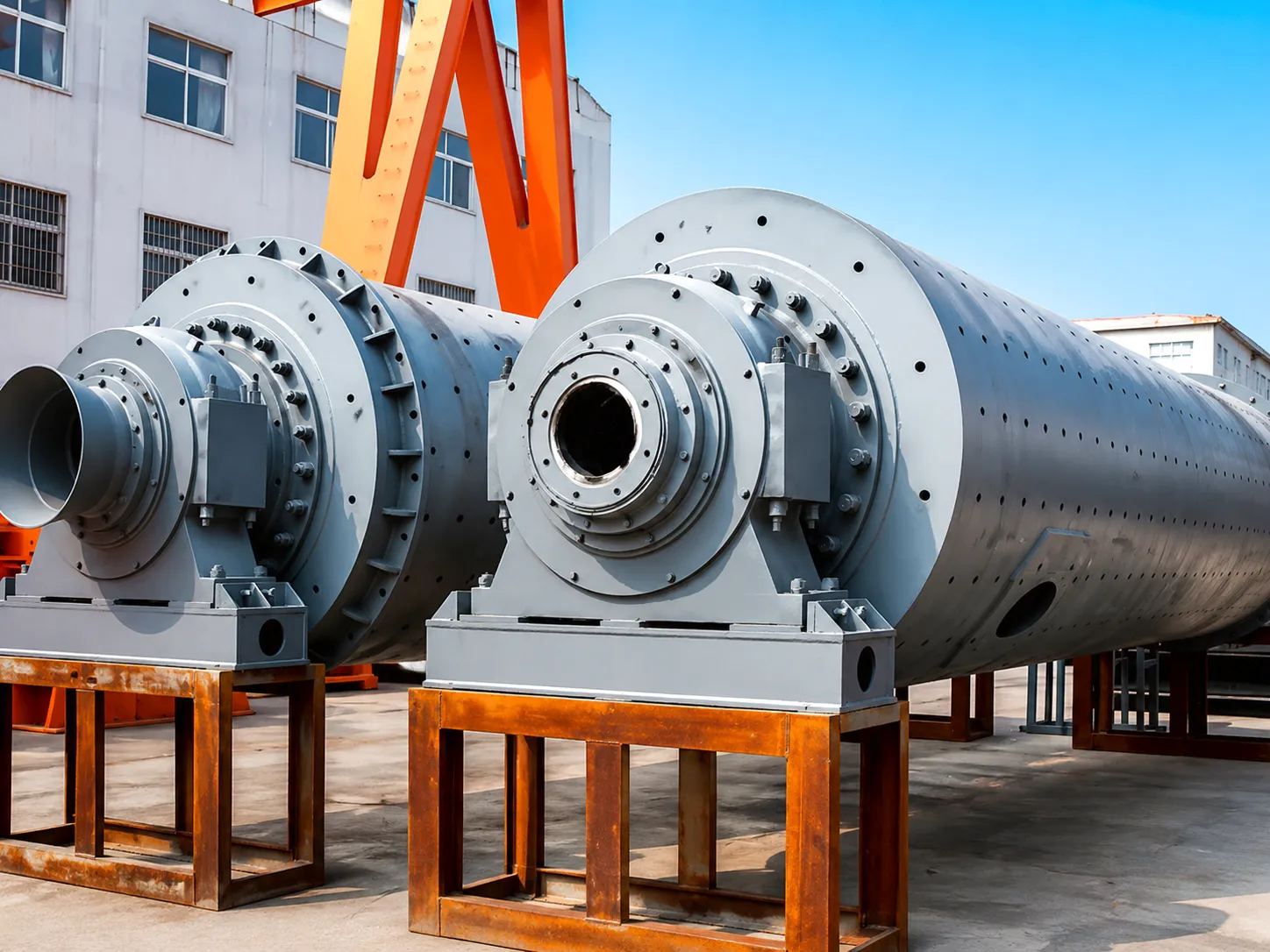
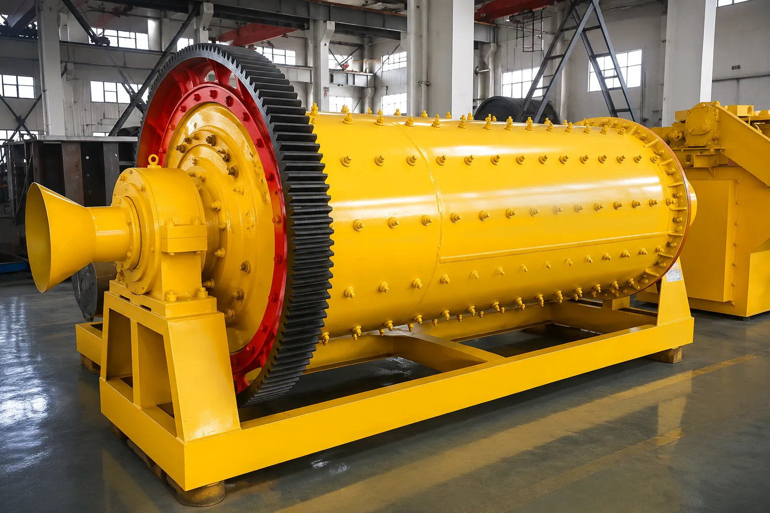
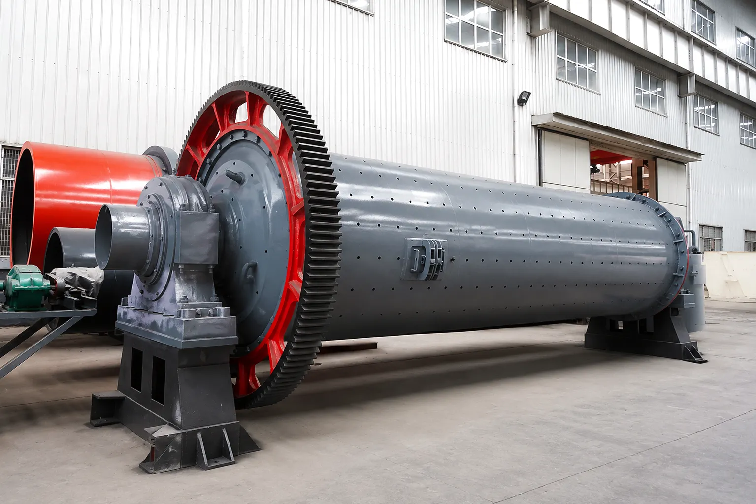
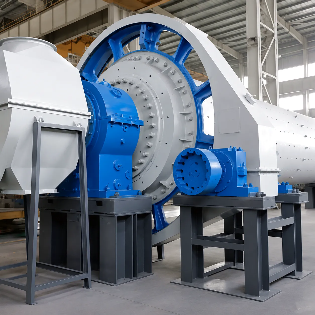 The cement grinding circuit in a modern UK plant is a cascade of interconnected mechanical sub-systems, each placing different demands on the coupling positioned within it. In a traditional ball mill arrangement — the type still found operating in plants across Derbyshire, Cumbria and North Wales — the primary drive train runs from a wound-rotor induction motor of 1,500 kW to 5,000 kW, through a semi-fluid coupling or a high-torque gear coupling, into a parallel-shaft reduction gearbox, and then via a slow-speed output shaft and open gear pinion into the mill shell. The gear coupling located on the high-speed input side of the gearbox operates at motor speed, typically 990 rpm to 1,485 rpm, and must transmit rated motor torque plus the overload multiplier during start-up sequences.
In a cement plant operating a ball mill of internal diameter 4.6 metres, the start-up inertia of the mill barrel and ball charge is enormous. When the motor is energised, the coupling must absorb an initial torque spike that may reach 2.5 to 3.0 times the steady-state operating torque before the mill reaches running speed. For a 3,000 kW motor operating at 1,000 rpm, that means the coupling must be capable of handling transient torque loads approaching 90 kN·m during the acceleration phase. Any coupling specified only to match the rated motor torque will be permanently fatigued within weeks of commissioning, leading to tooth pitting, micro-spalling and eventual sleeve fracture. The coupling selection service factor for cement mill ball mill drives in the UK industry is commonly set at a minimum of 2.5, incorporating start-up shock, drive system vibration, and angular misalignment contributions.
 Vertical roller mills, now the preferred technology for both raw material and cement grinding in modern UK projects, present a different coupling engineering challenge. The VRM drive arrangement places the gearbox directly beneath the grinding table, often with the motor mounted horizontally and connected to the gearbox by a horizontal shaft arrangement. The coupling in a VRM application must handle not only torque transmission but also significant levels of bending moment transmitted from the table through the gearbox to the motor shaft. This bending load component, generated by asymmetric grinding forces as the rollers track over varying material bed depths, rules out rigid flange couplings entirely. High-performance gear couplings with generous tooth crowning, or double-articulating universal couplings, are the preferred choice for VRM drives in plants such as those operated by leading UK cement producers at their facilities in Rugby, Hope Valley, and Dunbar, Scotland.
The dust environment in a cement grinding building places extraordinary demands on coupling sealing systems. Fine cement dust — with particle sizes predominantly in the 10 to 40 micron range — is highly abrasive and has a strong affinity for lubricating grease. Even a small breach in the coupling’s labyrinth seal allows dust ingress at a rate sufficient to turn the semi-fluid gear grease into an abrasive paste within a matter of weeks. UK plant experience consistently shows that abrasive grease contamination is the primary mechanism driving premature coupling tooth wear, and that coupling inspection intervals should specifically focus on seal integrity assessment. Double-labyrinth seal designs with an internal grease purge channel — a design feature that forces clean grease outward past the seal lip rather than relying entirely on the seal to block incoming dust — are strongly recommended for cement mill primary drive applications.
Technical Performance Parameters — Cement Mill Drive Couplings
The following table consolidates the principal performance parameters for the three coupling types most commonly deployed in UK cement mill drive applications. Data ranges reflect the standard product range available from established manufacturers, with the understanding that specific projects will require confirmed selections based on detailed torque, speed and bore geometry calculations.
| Parameter | Zahnradkupplung | Schlangenfederkupplung | Universal (SWC) Coupling |
|---|---|---|---|
| Nenndrehmomentbereich | 1,250 – 1,000,000 N·m | 160 – 250,000 N·m | 500 – 800,000 N·m |
| Maximale Winkelabweichung | 0.5° – 1.5° | 1.0° – 2.0° | 5° – 25° (single joint) |
| Max. Parallel Offset | 0.3 – 2.0 mm | 0.5 – 3.0 mm | Accommodated via angle |
| Max. Operating Speed | Up to 4,500 rpm | Up to 3,600 rpm | Up to 2,500 rpm at max angle |
| Nabenmaterial | 42CrMo4-Legierungsstahl | GJS-500 / 42CrMo4 | 42CrMo4 forged steel |
| Tooth Hardness (HRC) | 58 – 62 HRC | N/A (spring element) | 55 – 60 HRC (cross journals) |
| Betriebstemperatur | -20 °C to +120 °C | -30 °C to +100 °C | -25 °C to +150 °C |
| Max. Bore Diameter | Up to 400 mm | Up to 300 mm | Up to 360 mm |
| Schmierung | Semi-fluid gear grease (NLGI 0) | Dry / light oil film | Grease (NLGI 2) in cross bearings |
| Typical Maintenance Interval | 12 – 18 months | 24 – 36 months | 8 – 12 months (cross greasing) |
| Overload Capacity (Peak / Rated) | 3.0 – 3.5 x rated | 2.5 – 3.0 x rated | 2.5 – 4.0 x rated |
| Certification Standard | ISO 14691 / GB/T 5272 | GB/T 10614 | ISO 8792 / GB/T 5901 |
Core Engineering Advantages in Cement Mill Coupling Applications
Featured Coupling Products for Cement Mill Applications
Two products from our range stand out as particularly well-matched to the demands of cement mill drive engineering. Both are stocked and available for rapid despatch to UK destinations.
Ever Power: Precision Manufacturing and Custom Coupling Engineering
Ever Power operates a dedicated coupling manufacturing facility equipped with CNC gear hobbing and grinding centres, jig-bore machining with positioning repeatability of 0.005 mm, and full coordinate measuring machine (CMM) inspection infrastructure. This manufacturing capability allows Ever Power to produce gear coupling hubs and sleeves to quality standards that match or exceed the major European OEM standards referenced in UK plant engineering specifications, while offering the pricing and lead time flexibility that independent UK plant engineering teams and UK-based maintenance contractors increasingly require in the post-Brexit supply chain landscape.
Ever Power’s customisation capabilities for cement plant coupling applications are among the most comprehensive available to the UK market. Standard product lines cover bore sizes from 20 mm to 400 mm across all three coupling types. Beyond the standard range, Ever Power’s application engineering team provides a full custom coupling service: a customer submits shaft dimensions, torque and speed data, misalignment budget and dust ingress class from the site environmental survey, and the Ever Power engineering team returns a compliant coupling design within 5 working days, complete with a dimensional drawing, materials certificate and a service life calculation based on ISO 281 fatigue methodology. The design is then manufactured in Ever Power’s own facility with a quoted delivery lead time and full dimensional inspection report included in the despatch pack.
For UK procurement teams managing framework contracts across multiple cement sites, Ever Power offers consolidated supply arrangements under which agreed custom coupling configurations are held as pre-machined blanks in the Ever Power facility, with bore finishing and keyway cutting completed to confirmed order dimensions within 48 hours. This consignment-stock model, offered via a straightforward framework supply agreement, effectively gives UK plant operators the benefits of local stockholding without tying up working capital in slow-moving spares. It is a service model that resonates strongly with the procurement and engineering teams at multi-site UK operations where every site runs slightly different legacy shaft configurations and a single standard coupling rarely fits the whole fleet.
Customer Success Story: Rugby-Based Cement Plant Eliminates Repeat Coupling Failures
 A cement producer operating a twin ball mill circuit at their Rugby, Warwickshire site had experienced a recurring pattern of gear coupling tooth failure on the primary mill drive. Over a three-year period, four coupling sleeves had developed progressive tooth pitting that required unplanned replacements at an average cost of £38,000 per intervention including parts, labour and production loss. The site maintenance manager’s investigation identified two contributing factors: the original coupling had been selected using a service factor of only 1.8, insufficient for the site’s frequent direct-on-line start sequences during peak production periods, and the existing labyrinth seal design had proved inadequate against the extremely fine particle cement dust generated by the site’s high-efficiency separator operating circuit.
The maintenance team engaged Ever Power’s application engineering team with a full dataset: motor nameplate data (3,500 kW, 990 rpm, wound rotor), gearbox input flange dimensions, shaft keyway geometry, number of starts per month (averaging 22 cold starts), and the site’s ambient dust concentration measurement of 280 mg/m3 inside the mill building. Ever Power’s engineers calculated that the correct service factor for this application was 2.7, and specified a crowned-tooth gear coupling with a maximum bore of 320 mm, double-labyrinth seals with grease purge channels, and tooth profile finished to DIN 867 quality class 7 to ensure consistent load sharing across the full tooth count.
The replacement coupling was installed during the plant’s scheduled fortnight maintenance window in the autumn. The installation team at the Rugby site reported that the Ever Power coupling arrived pre-assembled with inspection plugs correctly fitted and a dimensional inspection report confirming bore and keyway dimensions to within 0.01 mm of drawing. Eighteen months after installation, at the subsequent annual inspection, the tooth flanks showed only normal running-in polish with no signs of pitting, spalling or abrasive scoring. The site has since ordered a second identical coupling as a bonded spare, replacing the previously fragmented approach of using whichever coupling could be sourced at short notice.
“The Ever Power gear coupling has gone eighteen months without a single grease top-up. The double-labyrinth seals are genuinely effective — this is the first coupling on that drive that has survived an annual inspection with clean grease still in the tooth mesh zone.”
“What set Ever Power apart was the application engineering support. They ran the service factor calculation for us and came back with a written recommendation supported by the ISO standard references. That gives us the documentation trail we need for our asset management system.”
“We had the coupling on site in four working days from confirming the bore dimensions. The inspection report was in the delivery pack and matched the drawing exactly. For a bespoke machined item that speed of supply is genuinely impressive — it let us hit our maintenance window without a day’s delay.”
Häufig gestellte Fragen
Questions commonly asked by UK plant engineers and procurement teams about cement mill couplings.
✉ Request a Coupling Quotation Now