
Application Scenario 13 · Industrial Drive Systems

Couplings in Thermal Power Generation: High-Speed, High-Torque Turbine-to-Generator Drive Solutions

How gear-type and flexible couplings meet the demands of continuous-duty turbine drive trains in the UK’s coal, gas, and combined-cycle power sector.

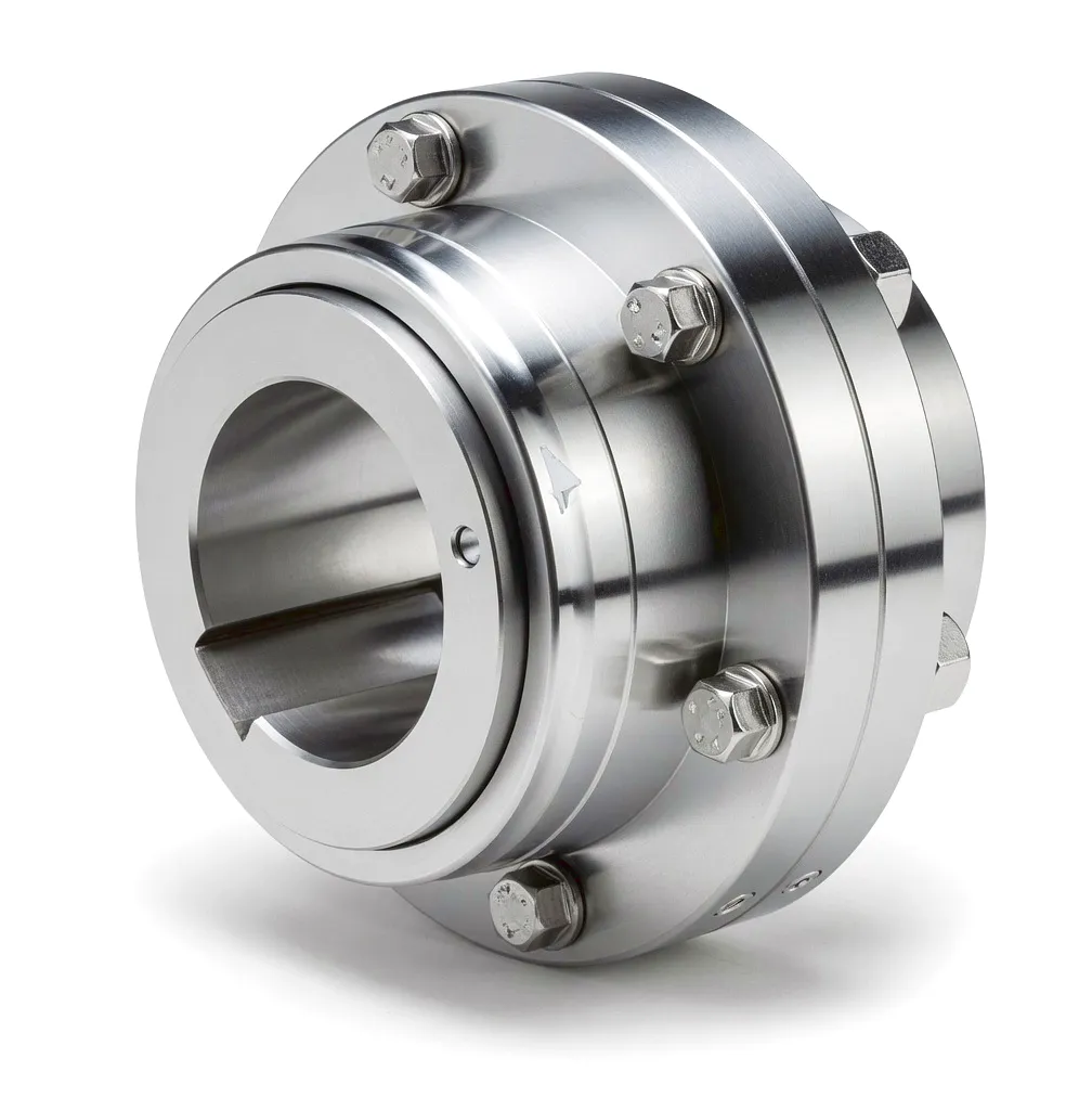
Gear type coupling for thermal power turbine driveInside any large thermal power station — whether a coal-fired plant in Yorkshire, a gas-fired combined-cycle facility in Teesside, or an industrial cogeneration site in the West Midlands — the connection between the high-speed steam turbine and the generator shaft is one of the most mechanically demanding joints in the entire energy industry. This single coupling must transmit several hundred megawatts of rotational energy at speeds typically ranging from 1,500 rpm to 3,600 rpm, while simultaneously accommodating the thermal expansion of a massive steel rotor operating at elevated temperatures. The consequences of failure are catastrophic: an unplanned trip can cost a UK power operator tens of thousands of pounds per hour in lost generation. That reality makes the selection of the right industrial coupling — and the precision engineering behind it — a strategic engineering decision rather than a commodity purchase.

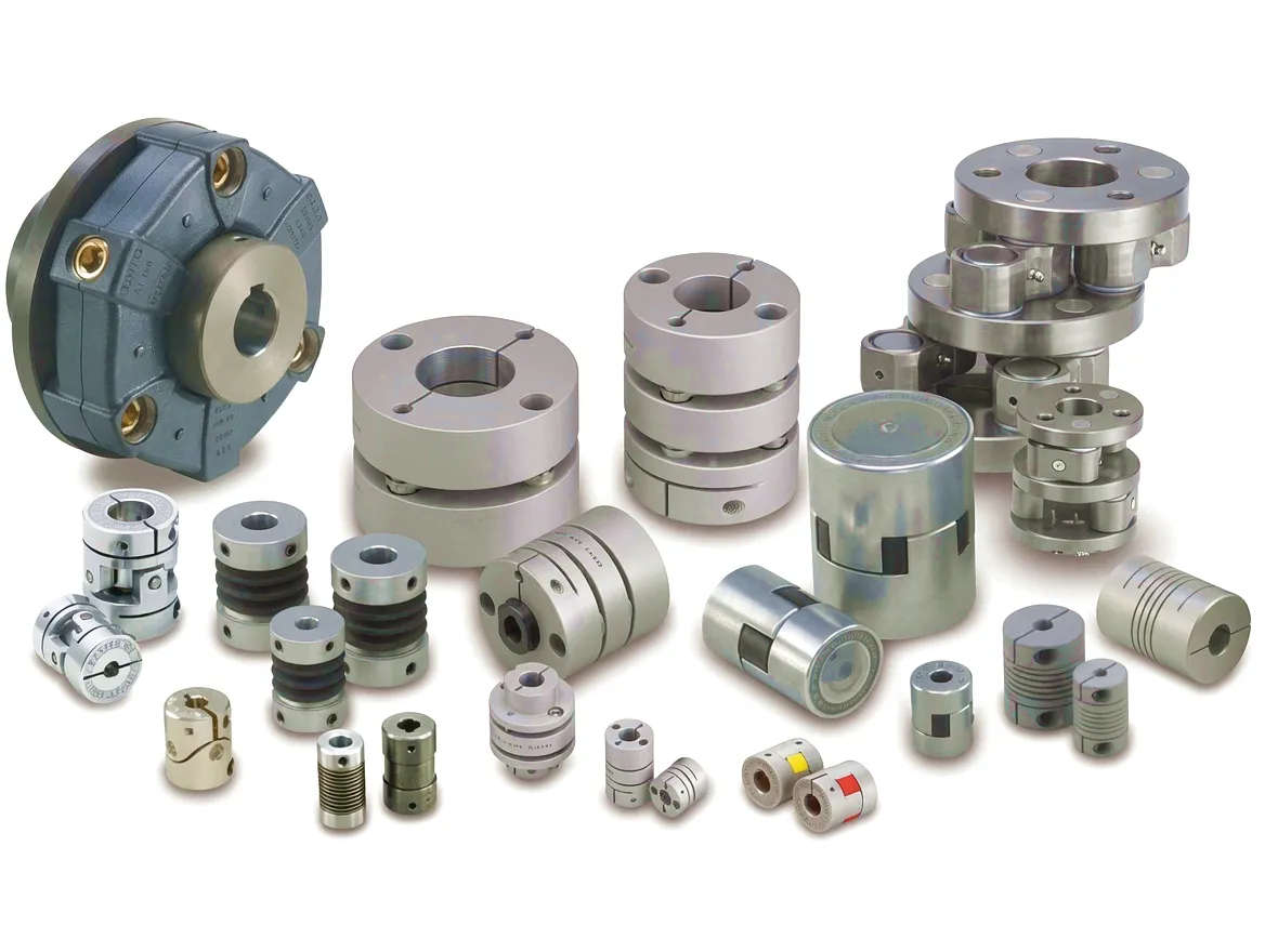
The term “coupling” in this context encompasses a family of precision mechanical components designed to connect two co-axial shafts, transmitting torque while managing three types of misalignment: angular, parallel (radial), and axial. In thermal power applications, the coupling also acts as a protective mechanical fuse in abnormal operating events, and its dynamic balance quality directly influences the vibration signature of the entire turbine-generator set. Utilities and EPC contractors across the UK increasingly specify gear-type couplings, disc couplings, and flexible beam couplings for various positions within the steam path, each chosen based on a precise evaluation of torque range, shaft diameter, thermal growth allowance, and fatigue life requirement.

Why Turbine Drive Couplings Demand a Different Engineering Approach
100,000 h+
Minimum Design Life
G2.5
Dynamic Balance Grade (ISO 1940)
500 MW+
Output Power Range

Industrial coupling for power generation driveA standard industrial coupling that performs perfectly well on a pump or compressor shaft will fail prematurely in a turbine-generator application. The operating environment is fundamentally different in several overlapping ways. The sheer magnitude of transmitted torque — reaching millions of Newton-metres on large utility-scale turbines — demands forged alloy steel components with tightly controlled metallurgical specifications. The continuous duty cycle eliminates any opportunity for scheduled wear compensation. And the rotor dynamics of a turbine-generator train are so sensitive to coupling-induced mass imbalance that even a small deviation from the specified balance grade can trigger sub-synchronous resonance, leading to bearing damage and forced outage.

Perhaps the most distinctive challenge, however, is thermal growth. When a steam turbine reaches its rated operating temperature — the high-pressure cylinder alone operates well above 500 °C in a modern supercritical unit — the turbine casing and rotor expand by measurable amounts along all three axes. The cold-alignment condition set during installation is, by design, an offset alignment chosen so that the shafts reach true co-axiality only at rated thermal conditions. The coupling must therefore accommodate significant angular and axial displacement every time the machine starts, runs at partial load, and eventually shuts down. Gear-type couplings, with their crowned tooth geometry, are specifically engineered to absorb these excursions without generating destructive restoring forces that would load the turbine and generator bearings asymmetrically.

How Gear-Type Couplings Work in High-Speed Turbine Drive Trains
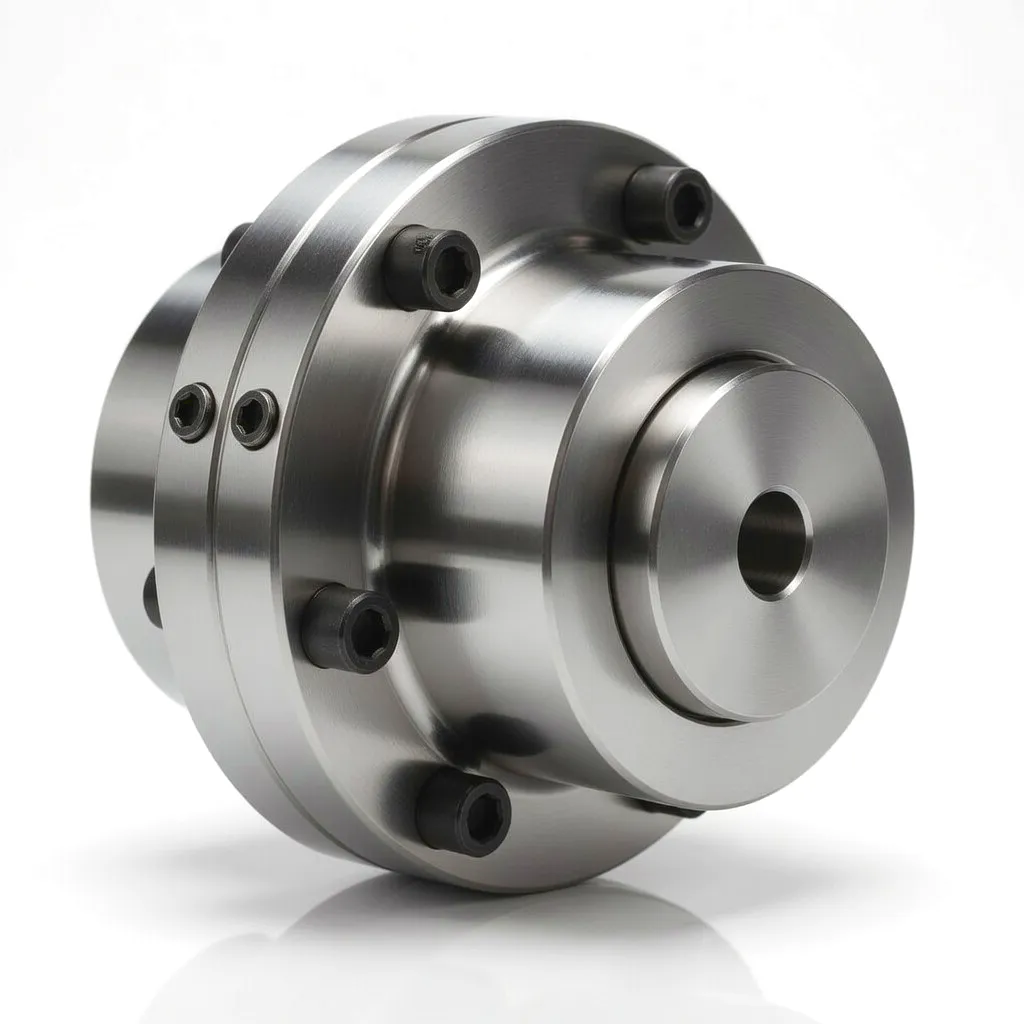
Gear coupling cross section turbine applicationThe gear-type coupling — also referred to as a gear coupling or toothed coupling — transmits torque through meshing teeth, very much like an internal spur gear pair, but with a crucial geometric modification: the teeth on the inner hub (the male component that fits on the shaft) are convex in profile when viewed along the coupling axis. This so-called crowned tooth geometry means that tooth contact is maintained even when the hub axis is angularly offset from the sleeve axis by up to 1.5 degrees, depending on coupling series and speed. Torque transfer occurs through the full circumferential array of teeth simultaneously, distributing the load and minimising contact stress.

In a typical thermal power coupling assembly, two internally toothed sleeves (sometimes called gear rings) mesh with two externally toothed hubs, one on the turbine end and one on the generator end. The sleeves are joined by a spacer tube or flange that bridges the gap between shaft ends — a feature particularly important during turbine overhauls, where the coupling spacer must be withdrawn without disturbing the rotor bearing alignment. Lubrication is critical: most high-speed gear couplings in utility power stations are continuously lubricated with turbine oil via an integral oil circuit, maintaining a hydrodynamic film between the gear teeth at all times. The lubricant also carries away the small frictional heat generated by angular displacement, preventing thermal degradation of the tooth flanks.

Axial displacement — caused by thermal growth along the shaft axis — is accommodated by allowing the male hub to translate axially within the female sleeve. In a well-designed coupling, this sliding action occurs with very low axial restraint force, ensuring that turbine thrust bearings are not subjected to additional load from the coupling. The combination of angular and axial flexibility, continuous lubrication, and high torque capacity makes the gear coupling the dominant choice for the main turbine-generator connection in large thermal power sets throughout the UK and internationally.

Core Materials in Thermal Power Coupling Manufacturing

Hubs & Flanges
42CrMo4 / 34CrNiMo6 Alloy Steel
Vacuum-degassed forgings with tensile strength 900–1,100 MPa. High fatigue resistance essential for 100,000-hour continuous duty. Fully heat-treated and normalised for dimensional stability.
Gear Sleeves
Case-Hardened 20CrMnTi or 18CrNiMo7-6
Carburised and quenched to achieve surface hardness HRC 58–62 on tooth flanks, maintaining a tough core. Ground tooth profiles to DIN 3962 Class 5 or better for precision meshing at high peripheral velocities.
Spacer Tube
Seamless Low-Alloy Steel Tube (S355 / EN 10297)
Precision-bored for concentricity better than 0.02 mm TIR. Wall thickness calculated to avoid critical resonance within the operating speed range. Dynamically balanced as a sub-assembly prior to final coupling balance.
Seals & Retainers
Nitrile / Fluorocarbon (FKM) Elastomers
Turbine oil-compatible sealing elements prevent lubricant leakage and ingress of steam condensate. FKM seals specified for applications where turbine oil operating temperatures exceed 120 °C continuously.

Application Scenario 13: Thermal Power Generation Drive Trains

Steam Turbine → Coupling → Generator | Continuous-Duty High-Speed Drive

Thermal power plant turbine coupling applicationIn the context of UK power generation, the turbine-to-generator coupling sits at the very heart of the conversion process — transforming the kinetic energy of high-pressure steam into electrical power that flows into the National Grid. On a typical 660 MW two-shaft arrangement, such as those operating at Drax Power Station in North Yorkshire or Cottam Development Centre in Nottinghamshire, the high-pressure and intermediate-pressure turbines drive one end of the coupling train, while the low-pressure turbines and generator form the other side. The coupling between the last LP turbine and the generator is often the most heavily loaded, carrying the full combined torque output at 3,000 rpm (for 50 Hz machines directly connected to the grid at two pole-pairs).

The thermal growth challenge in this application is not merely theoretical. During a cold start from standstill to synchronisation, the rotor temperature gradient creates differential thermal expansion between the turbine shaft — which heats up rapidly via steam conduction — and the surrounding casings. Field alignment records at UK power stations regularly document angular misalignment excursions of 0.1 to 0.3 mm/m during transient operating periods. The gear coupling must absorb these excursions without transferring bending moments back onto the rotor, which would manifest as vibration increases measurable on the proximity probe monitoring systems required by the turbine OEM and UK grid code guidelines.

For gas turbine combined-cycle units — increasingly prominent in the UK’s power mix as coal-fired capacity retires — the operating speed can reach 3,600 rpm on 60 Hz-equivalent export designs or involve a gearbox in the train. Here, disc couplings are frequently specified for the high-speed end of the gearbox output shaft, due to their torsional stiffness, zero-backlash torque transmission, and absence of lubrication requirements. The disc coupling’s metallic membrane transmits torque through elastic bending of the disc pack, making it inherently maintenance-free and highly resistant to the high-cycle fatigue associated with grid frequency fluctuations and load cycling in a modern half-hourly settlement market.

Core Technical Advantages of Gear-Type Couplings in Power Generation

Massive Torque Capacity
Gear couplings are rated for transmitted torques measured in millions of Newton-metres, with available bore sizes accommodating shaft diameters exceeding 600 mm. No other flexible coupling type matches this combination of compactness and torque density at high speed.
🔧
Three-Axis Misalignment Compensation
The crowned tooth design accepts simultaneous angular (up to 1.5°), axial (up to ± 15 mm), and parallel offset misalignment within a single compact envelope, making it uniquely suited to the three-dimensional thermal growth patterns of large turbine-generator sets.
🛡
Outstanding Fatigue Endurance
Purpose-engineered for cumulative service lives exceeding 100,000 operating hours without major overhaul. Case-hardened gear tooth surfaces resist pitting and micropitting fatigue, the predominant failure mode in continuously lubricated high-speed gear meshes operating under variable torque loading.
Precision Dynamic Balance
High-precision gear couplings for turbine service are dynamically balanced to ISO 1940-1 Grade G2.5 or better, with residual unbalance typically held below 1 g·mm per kilogram of rotating mass. This ensures the coupling does not contribute measurably to the rotor vibration signature at any speed within the operating range.
🔄
Spacer-Element Removal Without Rotor Disturbance
The spacer design permits extraction of the coupling centre section during turbine major overhauls without the need to disturb rotor bearing positions or re-align the machines from scratch, dramatically reducing planned outage duration and associated generation revenue loss for UK power station operators.
📊
Torsional Tuning Capability
The torsional stiffness of a gear coupling can be specified within a defined range by varying tooth geometry and engagement length, allowing rotor dynamics engineers to detune critical torsional natural frequencies away from excitation sources such as grid frequency multiples, generator pole-pass frequency, and LP blade passing frequencies.

Product Technical & Performance Parameters

The table below summarises typical design parameters for gear-type couplings specified in UK thermal power and heavy industrial turbine applications. Values represent standard production ranges; Ever Power engineering teams regularly manufacture to customer-specific requirements beyond these bounds.

ParametriSmall / Medium (SM)Large Industrial (LI)Utility Turbine (UT)Standard / Note
Nominal Torque (Nm)500 – 20,00020,000 – 500,000500,000 – 5,000,000+ISO 14691 / DIN 740
Peak Torque (Nm)Up to 40,000Up to 1,000,000Up to 10,000,000+Short-duration overload (2× Tn)
Suurin nopeus (rpm)Up to 6,000Jopa 4 5003,000 / 3,60050 Hz / 60 Hz grid-synchronous
Bore Diameter (mm)20 – 180180 – 400400 – 650+H7 tolerance, keyed or shrink-fit
KulmavirheJopa 1,5°Up to 1.0°Jopa 0,5°Per coupling face (total = 2× value)
Axial Travel (mm)± 3 – 8± 8 – 15± 15 – 30Lämpökasvun mukautuminen
Dynaaminen tasapainoluokkaG6.3G2.5G1.0 or betterISO 1940-1
Navan materiaaliC45 Steel42CrMo434CrNiMo6 / CustomEN 10083; vacuum-degassed forging
Tooth Hardness (HRC)28 – 32 (through)58 – 62 (case)58 – 64 (case + ground)Carburised and quench-hardened
Design Life (hours)25,00050,000100,000+Continuous operation, lube maintained

Beyond Turbine Main Shafts: Other Power Generation Coupling Applications

Industrial coupling in power generation auxiliary driveWhile the turbine-generator main coupling receives the most engineering attention, a large thermal power plant contains dozens of other coupling-dependent drive systems, each presenting its own set of technical demands. The boiler feed pump — one of the highest-powered auxiliaries on any power station, often rated at 10–30 MW — is typically driven through a hydraulic coupling or direct mechanical coupling to an electric motor or turbine driver. In the steam-driven boiler feed pump turbine (BFPT) arrangements common at UK 660 MW stations, the drive train from the BFPT to the feed pump includes a gear coupling with relatively high misalignment allowance, because the thermal growth of the pump casing under operating feed water temperatures of 230–250 °C creates significant vertical shaft displacement.
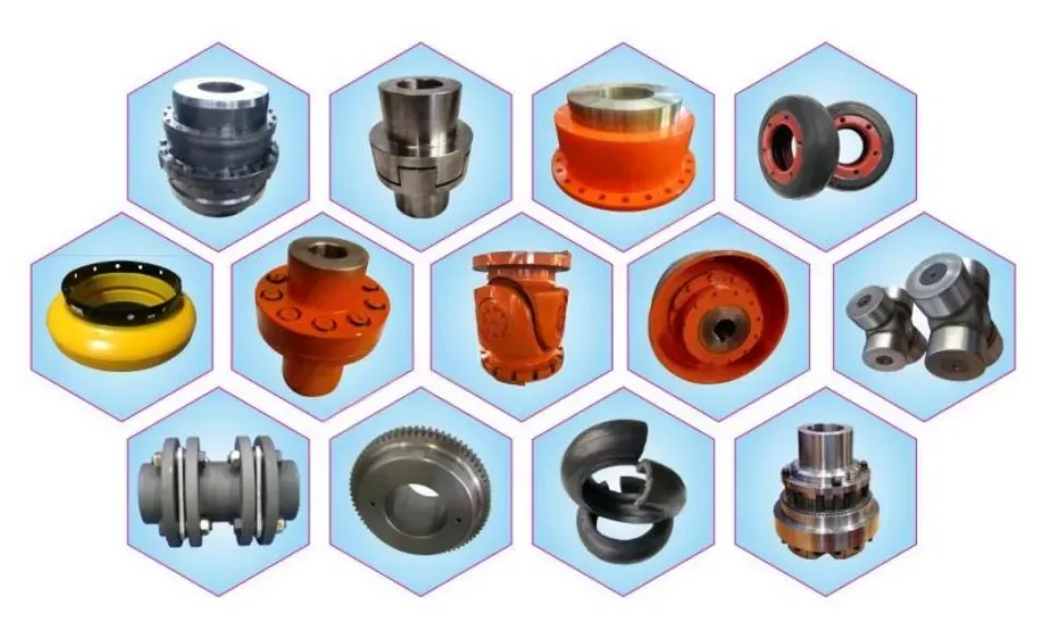
Induced draft fans, forced draft fans, and primary air fans — the ventilation machinery that maintains combustion airflow in coal-fired units — are driven through flexible shaft couplings connecting large induction motors to fan shafts spanning 3–6 metres. These couplings operate in an environment that is both thermally challenging and vibrationally demanding, with large fan imbalances caused by coal particle erosion of the blade tips imposing periodic shock torques on the coupling. Flexible beam couplings and elastomeric jaw couplings are frequently used in lower-power fan drive positions, while gear couplings are preferred on the largest fans where torque demands exceed the capability of elastomeric elements.

Cooling water pump drive trains, circulating water pump drives, and condenser extraction pump sets all rely on reliable coupling selections that must function without attention during the periods between major plant outages — typically 12 to 24 months in a modern UK station operating under a Plant Performance Agreement. The growing emphasis on rapid load-following capability in the UK market, driven by the National Electricity System Operator’s balancing mechanism requirements, means that these auxiliary drive couplings experience far more frequent start-stop cycling than was ever anticipated in the design era of baseload coal plant, placing premium importance on coupling fatigue design life and shock torque absorption capacity.

Ever Power coupling product range

The UK Power Generation Landscape and Coupling Supply Requirements

UK industrial power plant coupling application

The UK’s power generation sector is in active transition. The closure of the last operating coal-fired power stations — a process substantially advanced by the mid-2020s — has shifted coupling procurement patterns toward combined-cycle gas turbine (CCGT) facilities, offshore wind substations with diesel backup generators, pumped hydro storage facilities in Scotland and Wales, and a growing number of battery energy storage systems with grid-connected AC motor-generator sets. Each of these application types imposes different coupling selection criteria, and UK-based power plant operators and their engineering procurement contractors (EPCs) need coupling suppliers who can navigate this diversity.

Sheffield, long associated with precision steel manufacturing and specialist engineering, continues to host companies that specify high-performance couplings for the steel and energy sectors. Birmingham and the wider West Midlands manufacturing corridor generates significant demand for coupling supply into the power generation and heavy process industries, with a concentration of specialist rotating equipment contractors, maintenance engineering firms, and power station operators’ procurement functions within the region. In Scotland, the combination of North Sea energy infrastructure and onshore power generation creates substantial ongoing demand for couplings rated for harsh environment service.

UK EPC contractors and power station maintenance managers sourcing replacement couplings for steam turbine applications frequently need to match existing legacy designs — sometimes from equipment installed decades ago — while also demonstrating to their insurance and regulatory stakeholders that the replacement component meets or exceeds the original specification. This requires a coupling supplier capable of reverse-engineering from dimensional drawings, matching material certifications to original-equipment grades, and providing full material traceability documentation compliant with PED 2014/68/EU (retained in UK law as the Pressure Equipment (Safety) Regulations 2016) and relevant EN standards. Fast logistics from manufacture to site is a parallel requirement: unplanned turbine outages at UK power stations are extremely time-critical, and next-day or 48-hour despatch capability for stocked coupling sizes is increasingly treated as a prerequisite by plant maintenance teams.

Manufacturing Partner

Ever Power: Precision Coupling Manufacturing & Global Supply Chain

Custom Engineering
Every coupling Ever Power ships to UK power generation clients begins with a dedicated engineering review. Customers provide shaft drawings, torque data, speed range, and operating environment details. Ever Power’s application engineers then generate a full coupling selection report including torsional stiffness analysis, balance grade specification, and material certification schedule — at no additional charge to contracted customers.
Precision Manufacturing
Ever Power’s vertically integrated facility encompasses CNC gear hobbing, precision grinding, vacuum heat treatment, CMM dimensional inspection, and high-speed dynamic balancing up to 7,200 rpm. This in-house capability stack means the company maintains direct process control over every critical manufacturing step, without subcontracting heat treatment or tooth grinding to third parties who may not hold equivalent process certifications.
Supply Chain Assurance
Ever Power maintains a strategic stockholding programme for coupling hubs, sleeves, and standard spacer assemblies in the most commonly demanded size ranges for the UK power generation and heavy process sectors. This inventory, combined with DDP (Delivered Duty Paid) logistics partnerships serving major UK ports and freight forwarding hubs, enables rapid response to unplanned outage replacement demands — a critical differentiator for power station procurement teams managing generation availability risk.
Certification & Compliance
All couplings for UK power sector applications are manufactured under ISO 9001:2015 quality management. Material test certificates (EN 10204 Type 3.1) are provided as standard for all forgings and bar stock used in high-integrity coupling components. Dynamic balance certificates with residual unbalance data per plane are included in the shipping documentation package, supporting the customer’s handover records for turbine vibration baseline establishment.

Featured Ever Power Coupling Products

Two products within Ever Power’s range that address the overlapping demands of thermal power generation, precision industrial drives, and high-speed turbomachinery applications:
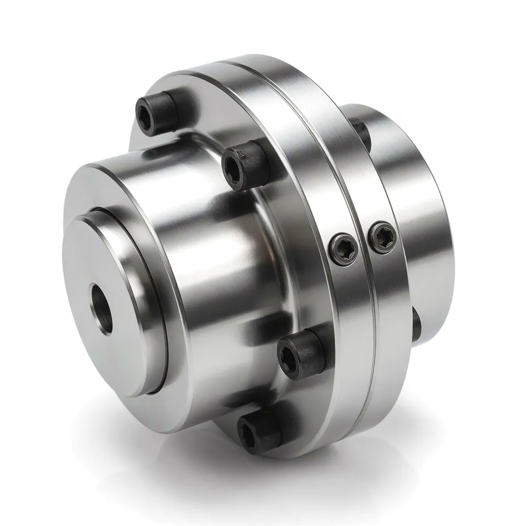
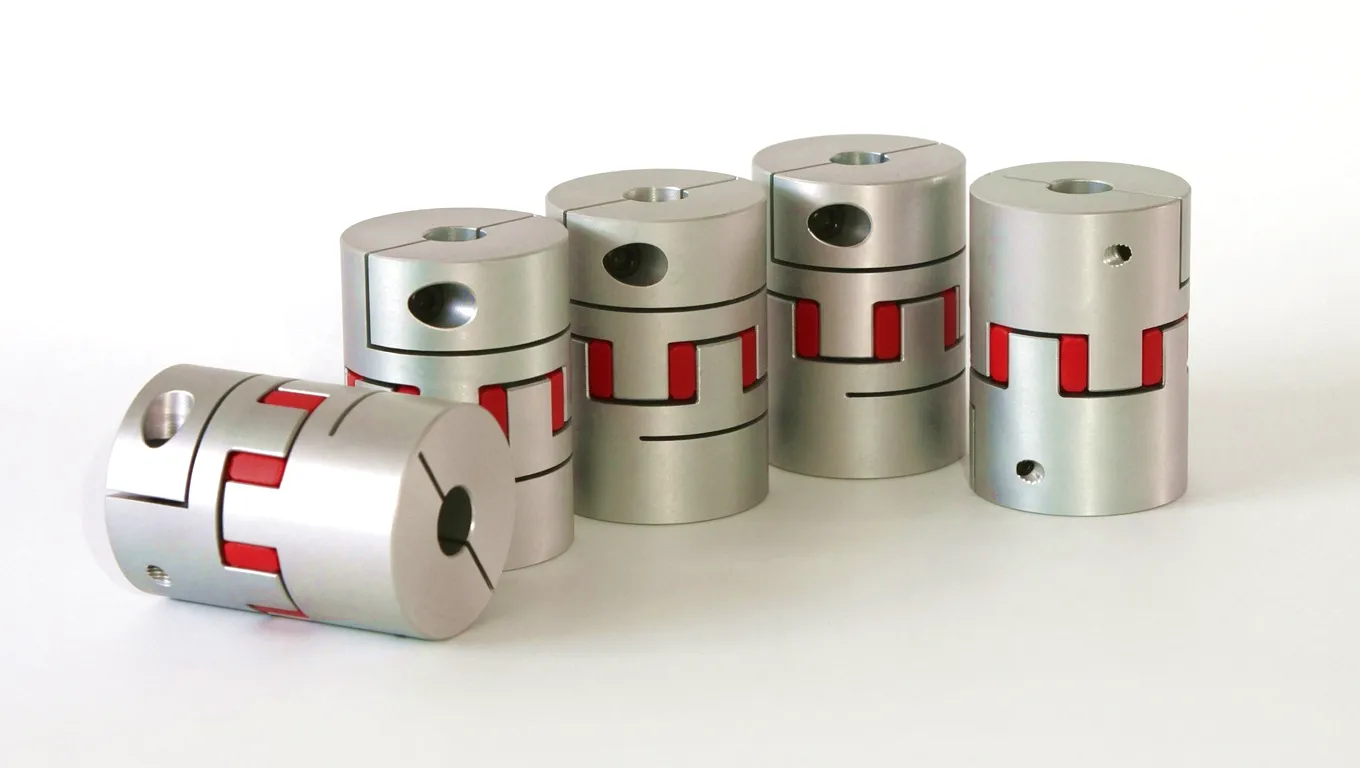
Flexible beam coupling Ever Power

The Joustava palkkikytkentä from Ever Power is machined from a single piece of high-tensile aluminium alloy or stainless steel, incorporating one or more helical beam cuts that provide angular, parallel, and axial flexibility without any sliding or rolling contact. This zero-backlash, maintenance-free design makes it ideal for servo motor drives, encoder connections, light-duty fan auxiliaries, and instrumentation drive trains within power generation control systems. The absence of any wearing contact surfaces means the coupling transmits positional accuracy reliably throughout its design life, making it a preferred choice for actuator feedback loops and metering pump drives in fuel gas conditioning systems.
View Product →

Disc coupling Ever Power

Ever Power’s Levykytkentä uses a pack of thin metallic disc elements — typically manufactured from 17-4 PH stainless steel or 15-5 PH — to transmit torque through elastic bending rather than contact meshing. This construction delivers torsional stiffness that is highly repeatable over the service life, supports operation without lubrication, and achieves dynamic balance grades of G1.0 or better due to the symmetric geometry of the disc pack assembly. In thermal power generation, disc couplings are the dominant choice for gas turbine compressor couplings, gearbox high-speed output connections, and generator exciter drive connections — applications where any maintenance intervention is an outage event and oil-lubrication piping to the coupling would represent an additional system complexity and fire risk.

View Product →

Customer Success Story: Teesside CCGT Unplanned Outage Recovery

Industrial coupling application in UK power generation

In the autumn of 2024, the rotating equipment maintenance team at a 900 MW combined-cycle gas turbine facility on Teesside — a critical asset supplying industrial power to the wider Northeast England chemical manufacturing corridor — detected an anomalous vibration signature during a routine data review using their online condition monitoring system. Proximity probe readings on the generator outboard bearing were trending upward, with a 1× vibration component increasing at a rate that projected exceedance of the trip setpoint within 14 days. Endoscopic inspection of the accessible coupling elements confirmed tooth wear beyond the acceptable limit on the gas turbine-to-gearbox gear coupling, a component that had accumulated approximately 87,000 hours of service since its last major inspection.

The plant’s engineering team contacted Ever Power with detailed dimensional drawings and original OEM specification sheets. Within 48 hours, Ever Power’s application engineering team had confirmed a direct replacement design using 34CrNiMo6 forgings for the hub elements, specified case-hardened tooth flanks ground to ISO Class 5, and committed to dynamic balance testing to G1.0 at the customer’s requested test speed. The full coupling assembly — hubs, sleeves, spacer tube, and hardware pack — was manufactured, inspected, balanced, and shipped within 11 working days of the confirmed purchase order, arriving at the Teesside site ahead of the scheduled replacement outage window.

The replacement coupling was installed during a planned 72-hour maintenance window. Post-installation vibration data showed 1× vibration on the generator bearing reduced to baseline levels within the first four hours of operation, and the unit returned to full load generation on schedule. The plant’s maintenance manager subsequently requested that Ever Power maintain a pre-agreed inventory of the two most common coupling sizes used at the facility, under a framework supply agreement that guarantees delivery within 5 working days from purchase order for standard dimensions — a supply arrangement that has since been cited internally as a model for the facility’s critical rotating equipment spares strategy.

★★★★★★

“The tooth surface finish and dimensional accuracy on the replacement hubs were measurably better than the original OEM components we removed after 87,000 hours. Balance certification data was clean — residual unbalance well within G1.0 on both planes. Post-installation vibration dropped to sub-alarm levels on first start. Highly recommend Ever Power for turbine coupling applications where you cannot afford a second bite of the cherry.”

Senior Rotating Equipment Engineer
CCGT Power Station, Teesside, Northeast England
★★★★★★

“We’ve been sourcing gear couplings from various suppliers for our Birmingham plant for fifteen years. The Ever Power team is the only one that proactively sent us a torsional analysis recommendation before we even asked for it — they spotted that our original coupling selection was creating a torsional natural frequency closer to our 3× running speed excitation than was ideal. The redesign has reduced our bearing replacement frequency noticeably. That kind of application engineering depth is genuinely rare.”

Mechanical Engineering Manager
Industrial Power Generation, Birmingham, West Midlands
★★★★★★

“We required a non-standard spacer length coupling for a Sheffield site retrofit where two different OEM machines had been connected during a capacity upgrade, creating an unusually wide shaft gap. Ever Power’s customisation capability handled this without any issue — full engineering package, custom spacer tube with confirmed subcritical lateral resonance at our 3,000 rpm operating speed, and 3.1 material certs for all components. Arrived on time and fitted first time. The framework supply agreement we subsequently set up has simplified our spares management significantly.”

Procurement & Contracts Manager
Power & Process Engineering Ltd, Sheffield, South Yorkshire

Usein kysytyt kysymykset

How do I work out what size gear coupling I need for a UK steam turbine generating 200 MW at 3,000 rpm?
The starting point is calculating the nominal torque using the formula Tn = (P × 9,549) / n, where P is the power in kilowatts and n is the speed in rpm. For 200 MW at 3,000 rpm, Tn ≈ 636,600 Nm. You then apply a service factor (typically 1.5 to 2.5 for turbine drives, depending on the severity of load transients) to obtain the design torque. This design torque value is used to select the coupling series from the manufacturer’s catalogue, which will also specify bore range, shaft interference fit, and dynamic balance requirements. Ever Power’s engineering team provides free coupling selection calculations for UK power generation customers — contact our team directly with your application data.
What is the typical cost or price range for a replacement gear coupling for a large utility turbine in the UK, and how long does it take to get a quote?
Gear couplings for utility turbine applications are precision-engineered components, and pricing is highly dependent on shaft bore diameter, spacer length, material grade, balance requirement, and urgency of supply. For replacement couplings in the 400–650 mm bore range with full documentation packages, budgetary figures typically range from several thousand to several tens of thousands of pounds sterling, reflecting the forging, machining, heat treatment, grinding, and balance testing content. Ever Power turns around formal quotations within 24 to 48 hours of receiving technical drawings and application data. For urgent outage situations, a preliminary budget indication can usually be provided within four working hours by email to our sales team.
Which type of coupling is better for a gas turbine compressor drive in the UK petrochemical sector — a gear coupling or a disc coupling?
For gas turbine compressor drives in petrochemical environments — a common arrangement at UK sites from Grangemouth to Teesside — the disc coupling is generally preferred over the gear coupling at the high-speed shaft connection. The disc coupling requires no oil lubrication, eliminating the risk of oil leakage in a potentially flammable atmosphere and removing a maintenance obligation from the drive train. Its zero-backlash, torsionally stiff character suits the dynamic response requirements of centrifugal compressor trains where surge margin and speed response characteristics are critical. Gear couplings remain appropriate where very large angular misalignment compensation is needed or where shaft bore sizes exceed typical disc coupling limits.
Where can I find a reliable flexible coupling supplier in the UK who can deliver to a Sheffield or Birmingham power station site quickly?
Ever Power operates a DDP logistics model to UK delivery addresses, working with established freight forwarding partners that offer regular consignment services to major UK industrial centres including Sheffield, Birmingham, Leeds, Manchester, and Teesside. Standard stocked coupling sizes can be despatched within 24 to 48 hours of purchase order confirmation. For custom or engineered-to-order couplings, typical lead times range from 7 to 15 working days depending on component complexity. UK power station customers and their approved contractors should contact our sales team directly to discuss framework supply agreements with pre-agreed lead times and pricing for their critical coupling sizes.
When should I replace the gear coupling on a thermal power turbine-generator, and what signs indicate the coupling is failing?
Turbine-generator gear couplings should be inspected at every major planned outage and replaced when tooth flank pitting exceeds 4% of the active tooth face area, when coupling-induced vibration contributes more than 30% of the total 1× synchronous vibration amplitude, or when dimensional inspection reveals tooth wear (reduction in tooth thickness at pitch circle) beyond the OEM or replacement supplier’s serviceable limit — typically 15–25% of the original tooth thickness. Early warning signs include gradual upward trending of 1× proximity probe readings that cannot be explained by process changes, oil sample analysis showing elevated metallic particles consistent with gear tooth wear, and thermal imaging of the coupling housing showing hot spots during operation. At the 100,000-hour design life boundary, coupling replacement is generally treated as mandatory regardless of condition inspection findings.
What documentation and certifications should I ask for when buying a turbine-grade coupling from a supplier for a UK power station application?
For turbine-grade couplings destined for UK power stations, the minimum documentation package should include: EN 10204 Type 3.1 material test certificates for all pressure-bearing or load-transmitting forged and bar components; heat treatment records including time-temperature cycle charts and hardness survey results; dimensional inspection report with CMM data confirming all critical fits and gear geometry within specification; dynamic balance certificate stating residual unbalance in g·mm per kilogram on both balance planes at the test speed; and a declaration of conformity to the applicable standards (ISO 14691, DIN 740, or API 671 for petroleum/gas sector applications). Ever Power provides the full documentation package as standard for power generation customers.

gzl:n muokkaama