Industrial Transmission Technology

Gear Type Couplings in Wind Turbine Applications: Engineering Precision for the UK’s Renewable Energy Sector

How advanced gear couplings deliver the torque capacity, misalignment tolerance, and operational longevity that modern wind energy infrastructure demands — from offshore installations in the North Sea to onshore wind farms across Scotland and Wales.

Wind Energy
Gear Couplings
UK Manufacturing
B2B Industrial

Gear type coupling for wind turbine drivetrain

The wind energy sector in the United Kingdom stands at the centre of the nation’s transition toward net-zero emissions. With installed capacity exceeding 28 gigawatts across onshore and offshore assets, wind generation now supplies a substantial share of British electricity. Behind every turbine that spins across the Scottish Highlands, the Welsh uplands, or the North Sea’s vast offshore fields, lies a complex drivetrain — and at the heart of that drivetrain sits the gear type coupling. These precision-engineered components transmit enormous torques, accommodate shaft misalignment caused by structural flex and thermal expansion, and must remain operational for decades under some of the harshest environmental conditions imaginable. A single coupling failure in a multi-megawatt offshore turbine can translate into days of lost generation, costly marine-vessel mobilisation for repairs, and significant warranty exposure. Specifying the right gear coupling — and the right manufacturing partner — is therefore not a purchasing decision but a strategic engineering commitment.

This article examines the engineering principles, material science, and real-world performance characteristics of gear type couplings as they apply specifically to wind turbine drivetrains. It draws on application data relevant to the UK market and addresses the procurement considerations that engineering managers, OEM designers, and maintenance planners across Birmingham, Sheffield, Hull, and beyond need to make confident sourcing decisions.

How Gear Type Couplings Work in Wind Turbine Drivetrains
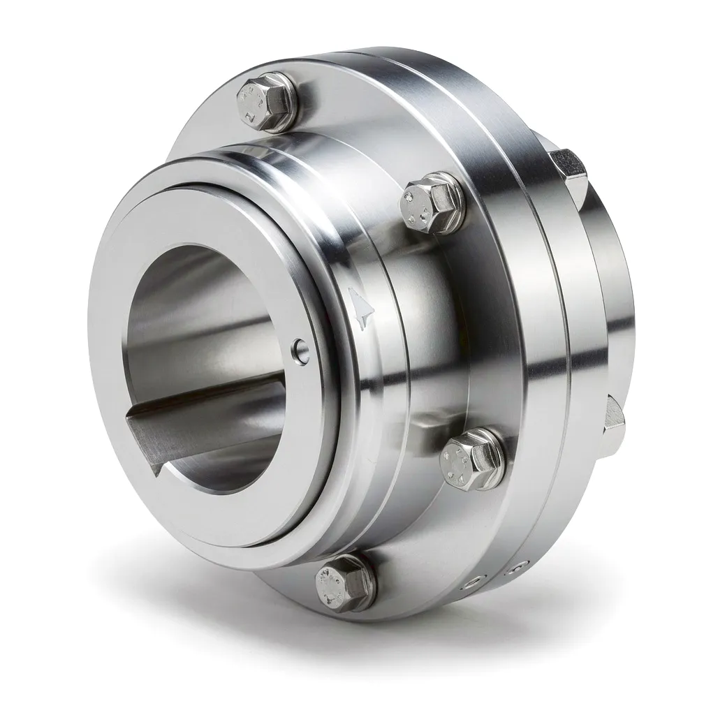
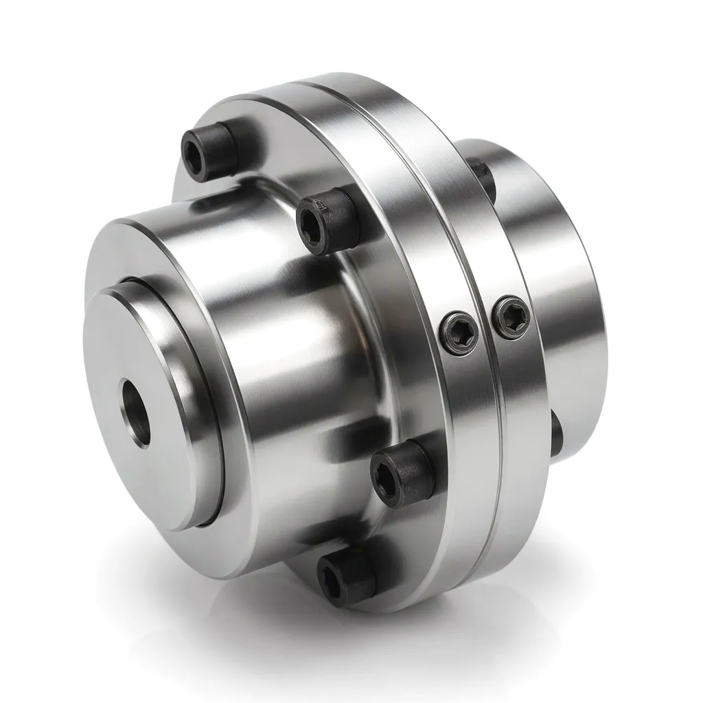
Internal gear coupling tooth engagement

A gear type coupling operates through the meshing engagement of internally toothed outer sleeves with externally toothed hubs, creating a mechanical linkage that transmits rotational torque while simultaneously allowing controlled angular, parallel, and axial displacement between two connected shafts. In a wind turbine drivetrain, this coupling typically bridges the main gearbox output shaft and the high-speed generator input, though gear couplings also appear in the low-speed shaft stage, yaw drive systems, and pitch control assemblies on larger turbines. The fundamental principle relies on the crowned tooth profile — a subtle convex curvature machined into the external gear teeth that allows the mating surfaces to rock and slide within the internal sleeve, absorbing misalignment without generating significant bending moments that would otherwise propagate into adjacent bearings and shaft seals.

When wind loading causes the turbine nacelle to deflect, or when thermal gradients across a long main shaft produce differential expansion, the gear coupling accommodates these movements dynamically and continuously. The tooth-to-tooth contact distributes load across multiple engagement points simultaneously, achieving torque transmission efficiencies typically above 98% even under misaligned operating conditions. Lubrication — either grease-packed or oil-lubricated depending on the installation — reduces tooth wear and dissipates heat generated at the contact interface. In offshore applications particularly, the integrity of the sealing system that retains lubricant and excludes salt-laden moisture is as critical as the metallurgical quality of the teeth themselves.

The coupling’s capacity to operate under the highly cyclical, variable-amplitude loading that characterises wind energy generation is what sets it apart from rigid alternatives. Turbine torque fluctuates with every gust, with rotor blade passing frequency, and with grid-demand transients. A gear coupling’s inherent mechanical compliance, combined with precise tooth geometry and surface treatment, absorbs these oscillations without transmitting destructive shock loads into the gearbox and generator bearings — a critical attribute for achieving the 20-to-25-year design lives demanded by wind farm developers and financiers alike.

Core Materials in Wind-Grade Gear Coupling Manufacture

● Alloy Steel (42CrMo4 / EN19)

The workhorse material for high-torque gear coupling hubs and sleeves. Chromium-molybdenum grades are quench-and-tempered to tensile strengths of 900–1100 MPa, delivering the fatigue resistance needed for tens of millions of load cycles over a turbine’s operational lifetime. The material’s excellent machinability also allows the tight tooth profile tolerances that efficient power transmission demands.

● Carburised & Case-Hardened Steel

For applications demanding surface hardness beyond what through-hardening provides, carburising introduces carbon into a low-alloy steel matrix before hardening to achieve tooth-surface hardness of HRC 58–62 with a tough, ductile core. This gradient structure maximises wear resistance at the contact interface while retaining the toughness that prevents catastrophic brittle fracture under shock loading.

● Stainless & Duplex Grades

Offshore wind turbines in the North Sea operate in a highly aggressive marine environment where conventional carbon steels corrode rapidly without extensive protective coatings. Duplex stainless steel grades (e.g. 2205) offer a combination of high mechanical strength and chloride corrosion resistance that makes them well suited for sleeves and housings exposed to salt spray ingress, particularly in splash-zone installations on offshore jacket structures.

● Ductile Iron Variants

For medium-power applications and auxiliary drive systems within wind turbines — such as cooling fan drives and yaw motor connections — spheroidal graphite (SG) ductile iron offers a cost-effective balance of strength (tensile strength typically 400–600 MPa), excellent vibration damping, and castability that allows complex sleeve geometries to be produced efficiently. SG iron’s graphite nodules also provide an element of inherent self-lubrication under marginal lubrication conditions.

Surface treatments play an equally significant role. Phosphate conversion coatings, zinc-nickel electroplating, and advanced polymer-based anti-corrosion treatments are routinely applied to gear coupling components destined for offshore service. High-performance synthetic greases — lithium-complex or polyurea-based formulations rated to operate between -40°C and +150°C — are specified to ensure consistent lubrication film integrity across the wide temperature range encountered during North Sea operations, from winter gales to nacelle interior heat during high-power generation.
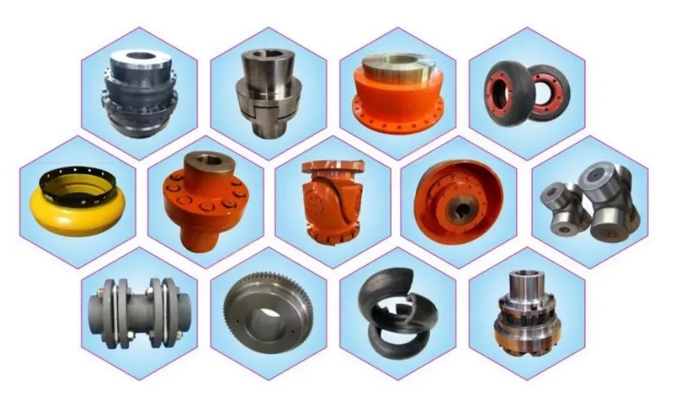
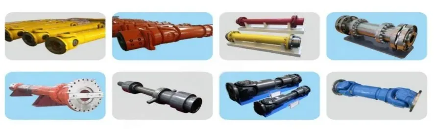
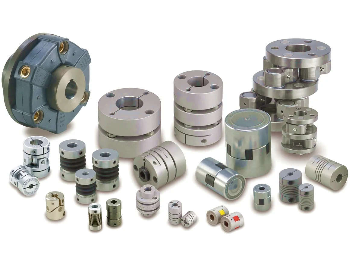
Ever Power gear coupling product range
Industrial gear coupling assembly

Core Technical Advantages for Wind Turbine Applications

01

Densité de couple élevée

Gear couplings achieve torque-to-weight ratios that flexible disc or elastomeric couplings cannot match at equivalent shaft sizes, making them the preferred choice for multi-megawatt turbine main shafts where weight and envelope are tightly constrained.

02

Multi-Axis Misalignment Tolerance

Angular misalignment capacity of up to 1.5° per coupling element — and parallel offset compensation — protects gearbox and generator bearings from the additional radial and axial loads that structural deflections and installation inaccuracies would otherwise impose.

03

Fatigue Endurance

Properly specified and lubricated gear couplings demonstrate fatigue lives exceeding 10^8 load cycles under rated torque conditions — a requirement that maps directly onto a 20-year turbine life at typical rotor speeds and partial-load duty cycles characteristic of UK wind patterns.

04

Compact Axial Envelope

The relatively short axial stack length of a gear coupling allows drivetrain designers to optimise nacelle length and mass — critical parameters for both transport logistics on UK road networks and the structural loading imposed on the tower and foundation during wind events.

05

Field Serviceability

Split-sleeve designs enable re-lubrication and inspection without dismantling the complete drivetrain — a practical advantage that significantly reduces crane time and technician hours during scheduled maintenance campaigns on both onshore and offshore UK assets.

06

Speed Range & Balance

Precision-balanced gear couplings maintain acceptable vibration levels across the wide speed range that a variable-speed turbine traverses — from cut-in speeds of approximately 3 m/s wind to rated operation above 11 m/s — without introducing resonance that could excite tower or foundation structural modes.

Technical & Performance Parameters — Wind-Grade Gear Couplings

ParamètreSpecification RangeNotes / Wind Application Context
Couple nominal500 Nm – 2,500,000 NmCovers auxiliary drives through to main-shaft couplings in 10 MW+ offshore turbines
Peak / Overload TorqueUp to 2.5 x rated (momentary)Grid fault ride-through events generate transient torque spikes requiring high overload margin
Maximum Rotational SpeedUp to 6,000 rpm (high-speed shaft)Precision dynamic balancing to ISO 1940 G6.3 or better at operating speed
Capacité de désalignement angulaireUp to 1.5° per elementAccommodates nacelle structural deflection and installation tolerance
Capacité de compensation parallèleUp to 5 mm (size-dependent)Manages thermal growth differentials between gearbox and generator housings
Déplacement axial±3 to ±15 mmPrevents axial thrust loads transmitting to gearbox or generator bearings
Matériau du moyeu42CrMo4, 18CrNiMo7-6, Duplex SS 2205Material selected based on torque level, speed, and corrosion environment
Matériau de la mancheAlloy steel, SG ductile iron, forged steelForged construction preferred for critical offshore applications
Dureté de la surface des dentsHRC 58–62 (carburised) / HRC 30–38 (induction)Higher surface hardness extends tooth wear life under cyclic loading
Plage de températures de fonctionnement-40°C to +150°CWide range covers cold-climate offshore startup to nacelle interior in summer generation
Type de lubrificationLithium-complex grease / polyurea grease / oil-bathGrease-packed designs typical for offshore; oil-bath for very high-speed applications
Re-lubrication Interval12–36 monthsExtended intervals reduce offshore vessel mobilisation cost
Protection contre la corrosionPhosphate, Zn-Ni, epoxy coating, stainlessCoating system selected to C5-M (marine) corrosivity category per ISO 12944
Transmission Efficiency> 98% at rated loadMinimal power loss contributes to overall turbine energy yield
Design Life20–25 years (wind application)Aligned with standard turbine design life per IEC 61400-1

Application Scenario: Wind Turbine Drivetrain Systems

Detailed engineering & operational analysis for gear coupling deployment across wind energy installations

Application Scenario 1: High-Speed Shaft Coupling — Gearbox to Generator Interface

Wind turbine gearbox to generator gear coupling

The high-speed shaft that connects the output of the turbine’s main gearbox to the generator input represents the most mechanically demanding coupling position in the entire drivetrain. At this interface, rotational speeds can reach 1,500 to 1,800 rpm for fixed-speed generators or up to 3,000 rpm on some converter-fed designs, while simultaneously transmitting torques that may reach hundreds of thousands of Newton-metres on machines rated above 5 MW. The gear type coupling at this location must handle not only the steady-state transmission requirements but also the severe dynamic loading that arises from grid-fault events, sudden load rejection, and the variable torque signature imposed by rotor aerodynamics as blades sweep through regions of wind shear.

On UK offshore installations — notably those operating on the Hornsea, Dogger Bank, and East Anglia Array projects in the North Sea — maintenance access windows are determined by vessel scheduling, weather windows, and air-traffic-control constraints on helicopter operations. Engineering teams based in Hull and Aberdeen understand that any coupling that reduces mean time between maintenance interventions directly reduces the cost per megawatt-hour of generated electricity over the project’s operational lifetime. Gear couplings specified with long-life grease and sealed sealing arrangements have proven instrumental in extending drivetrain service intervals on these remote offshore assets, delivering measurable improvements in availability figures and reducing operations-and-maintenance expenditure for asset owners.

Application Scenario 2: Low-Speed Main Shaft Couplings on Direct-Drive and Hybrid Architectures

Low speed main shaft coupling wind turbine

While direct-drive turbine architectures eliminate the main gearbox entirely and use large-diameter permanent-magnet generators matched directly to rotor speed, the hybrid medium-speed drivetrain concept — increasingly popular with European manufacturers supplying the UK offshore market — uses a compact, single-stage or two-stage gearbox that steps up rotor speed moderately before reaching a medium-speed generator. In this configuration, the coupling between the rotor hub’s main bearing and the gearbox input, and between the gearbox output and the generator, must both accommodate very high torques at relatively low speeds on the rotor side, transitioning to moderate torques at intermediate speeds on the generator side.

At these lower rotational speeds, the dynamic balance requirements are less stringent, but the absolute torque magnitudes are substantially greater — reaching multi-megawatt-hour values on the largest current-generation offshore turbines. Gear couplings in this service must be designed with generous service factors to accommodate the extreme fatigue loading associated with turbulent wind conditions over the Beaufort-scale storms common to UK waters, while also tolerating the rotor thrust and bending moments that cause the main shaft to deflect under asymmetric aerodynamic loading across the rotor disc. Manufacturers servicing wind OEMs from Sheffield’s precision engineering heritage and Birmingham’s advanced manufacturing base have developed particular expertise in the heavy forging and precision machining operations required to produce couplings at this scale.

Application Scenario 3: Yaw Drive Systems — Controlled Orientation in Variable Wind Conditions

Wind turbine yaw drive gear coupling application

Wind turbines continuously adjust their nacelle orientation to face the prevailing wind direction through yaw drive systems — an array of electric motors, gearboxes, and pinion drives that engage a large-diameter ring gear mounted to the tower top. The gear couplings within each yaw drive motor-to-gearbox interface are subjected to a fundamentally different duty cycle from the main drivetrain: they operate intermittently, often at low duty ratios, but must transmit full rated torque reliably after extended periods of standstill — potentially in sub-zero temperatures during Scottish winter conditions — and must resist shock loads generated by gusty, directionally shifting winds that impose high transient demands on the yaw system during periods of rapid wind veer.

The corrosion environment within the nacelle base, where the yaw drives are located, is typically less severe than the external faces but still requires attention to moisture ingress and condensation management. Gear couplings selected for yaw duty are usually more compact than main-shaft designs and may incorporate angular-contact variants that handle the combination of torque and the bending that results from the overhung loading inherent in the motor-pinion arrangement. UK-based wind operations teams — supporting assets from the Shetland Islands to Somerset — have fed valuable field data back to coupling manufacturers that has informed the development of specialised yaw-duty variants with enhanced starting torque characteristics and improved low-temperature grease performance.

Application Scenario 4: Pitch Control Actuator Drives — Individual Blade Angle Management
Pitch control coupling wind turbine blade

Modern variable-pitch wind turbines regulate power output and protect against overloads by continuously adjusting the pitch angle of each rotor blade through independent electric or hydraulic pitch actuator systems. The gear couplings within the electric pitch drive — linking the pitch motor to the pitch gearbox, and the gearbox output to the pitch ring gear pinion — must operate within the limited space available inside the rotating hub and must function reliably through the millions of pitch adjustment cycles that accumulate over a turbine’s operational life. A large offshore wind turbine’s pitch system may execute tens of thousands of pitch adjustments per day in turbulent conditions, placing significant demands on coupling fatigue life even at the relatively modest torque levels characteristic of pitch drives.

The pitch environment also introduces a rotational reference frame — the couplings spin with the hub at rotor speed while simultaneously transmitting pitch actuator torque — and must retain their lubricant against centrifugal forces that act to expel grease from the tooth mesh zone. Centrifugal grease retention features, including specialised labyrinth-type seals and grease retention plugs within the tooth flanks, are engineering solutions developed specifically for this demanding application context. UK wind turbine maintainers, particularly those supporting older assets from the early wind farm developments in Cornwall, Cumbria, and Wales, frequently cite pitch coupling serviceability as a key factor in the cost-effectiveness of life-extension programmes applied to turbines approaching their original design life.

Application Scenario 5: Hydraulic Pump & Cooling Fan Drives in Nacelle Auxiliary Systems

Nacelle auxiliary drive gear coupling cooling system

Beyond the primary power train, every wind turbine nacelle contains a range of auxiliary drive systems that rely on gear couplings to connect electric motors to hydraulic pumps, cooling fans, oil circulation pumps, and condition monitoring equipment. These auxiliary systems play a critical role in the overall reliability picture: a hydraulic pump coupling failure can prevent blade feathering, triggering an emergency shutdown and potentially causing a loss-of-production event that persists until a service vessel can reach the turbine. Gear couplings in auxiliary service are typically smaller and operate at lower torques than main-shaft designs, but the same principles of material quality, lubrication integrity, and misalignment tolerance apply.

The nacelle interior environment — subject to temperature cycling as generation levels fluctuate, vibration transmitted through the nacelle bedplate from the main drivetrain, and occasional moisture ingress through ventilation systems — presents its own set of challenges distinct from the external corrosion environment faced by offshore structural components. Gear couplings in this service typically require less frequent maintenance than main-shaft units, but their accessibility is often limited by the cramped nacelle layout of modern turbines, making compact designs with straightforward lubrication access points particularly valued by UK operations and maintenance contractors working across distributed fleets of turbines with minimal on-site tooling resources.

Ever Power: Precision Manufacturing & Custom Gear Coupling Solutions

Engineering partnerships built on manufacturing capability, not catalogue limitations

Full-Spectrum Customisation

Ever Power’s engineering team works from customer-supplied shaft data, OEM drawings, or performance specifications to design and manufacture gear couplings entirely tailored to the application. Non-standard shaft diameters, unusual keyway configurations, specialised bore tolerances, and bespoke flange patterns are all accommodated within standard project lead times. This capability is particularly valued by UK wind turbine operators managing legacy fleet assets where original coupling specifications are obsolete or where original equipment manufacturers no longer support legacy platform variants.

Precision CNC Machining & Gear Grinding

Ever Power operates CNC turning centres, gear hobbing machines, and precision gear grinding equipment that achieve tooth profile tolerances to DIN 5480 quality class 6 and above. Ground tooth profiles reduce surface roughness to Ra 0.4 µm or better, minimising lubrication film breakdown risk at tooth contact zones — a critical factor in achieving the extended re-lubrication intervals that reduce operational costs for offshore wind asset owners on annual fixed-price O&M contracts.

📜

Material Certification & Traceability

Every coupling supplied by Ever Power for wind applications is manufactured from materials with full mill certification traceable to recognised international standards. Mechanical property test certificates, hardness survey reports, non-destructive examination records, and dimensional inspection certificates are supplied as standard, providing the complete documentation package demanded by wind energy project certification bodies including DNV, Bureau Veritas, and Lloyd’s Register operating in the UK offshore certification environment.

Reliable Supply Chain & Delivery

Ever Power’s supply chain management capability covers raw material procurement, heat treatment sub-contracting, surface treatment coordination, and final assembly inspection — all managed through a structured quality management system. International logistics expertise, including sea freight to UK ports at Immingham, Felixstowe, and Southampton, ensures that UK-based wind energy procurement teams receive components with lead times and delivery reliability compatible with planned maintenance shutdown schedules and vessel charter windows.


📧 Request a Custom Coupling Quotation from Ever Power

Email: [email protected] | Rapid response for B2B engineering enquiries

Featured Related Products

Complementary drive components for wind turbine drivetrain systems from Ever Power

PTO Gearbox

HC-RC31 PTO Gearbox

A high-performance PTO gearbox designed for demanding power take-off applications. The HC-RC31 offers robust torque handling capacity with a compact, field-serviceable design that suits a range of industrial drive configurations including auxiliary systems within wind turbine nacelles and agricultural machinery. Its precision gear trains and sealed housing make it well suited to environments where maintenance access is limited.

View HC-RC31 →

PTO Gearbox

HC-RC30-193 PTO Gearbox

The HC-RC30-193 is a precision-engineered PTO gearbox offering a specific gear ratio configuration optimised for intermediate-speed drive applications. Its heavy-duty output shaft bearings and sealed housing construction make it an effective power transmission component for demanding industrial settings, including wind turbine auxiliary drives, agricultural PTO systems, and hydraulic pump drives operating under sustained load conditions across the full duty cycle.

View HC-RC30-193 →

Customer Success Story: Hull, East Yorkshire — Offshore Wind Operations

A wind energy operations and maintenance contractor based in Hull — a city that has positioned itself as one of the UK’s primary offshore wind industry hubs — was managing a fleet of 3.6 MW turbines across two North Sea wind farms. Over successive annual major maintenance campaigns, the engineering team had observed accelerating wear on the high-speed shaft gear couplings supplied by the original turbine manufacturer. Inspection records documented increasing backlash, lubricant degradation at intervals shorter than the specified re-greasing schedule, and two complete coupling replacements in a single season across the fleet — each replacement requiring a jack-up vessel mobilisation at significant cost and with consequent generation losses during the replacement window.

The operations director engaged Ever Power to review the application specification and propose an enhanced replacement solution. Ever Power’s engineers conducted a detailed analysis of the original coupling’s performance data, the turbine’s operational loading history extracted from the SCADA system, and the specific environmental conditions at the installation site — including the nacelle internal temperature profile, the frequency distribution of load cycles, and the lubricant grade historically specified. Based on this analysis, Ever Power proposed a custom gear coupling manufactured from 18CrNiMo7-6 carburised and case-hardened steel, incorporating an improved crowned tooth geometry with tighter profile tolerances, a sealed grease retention design with laboratory-validated 24-month service interval at the actual operating conditions, and a duplex zinc-nickel protective coating on external surfaces.

A pilot batch of twelve couplings was supplied for installation across a representative sample of turbines during the next major maintenance window. After 26 months of continuous service monitoring, condition assessments performed by the operations team revealed tooth wear rates approximately 40% lower than the baseline documented on the original equipment, with lubricant condition remaining within specification at the 24-month inspection interval. The operations director estimated that the improved coupling performance, combined with the extended service interval, reduced the fleet’s annual coupling-related maintenance expenditure by over 30% compared with the baseline established over the three preceding seasons. Satisfied with these outcomes, the contractor extended the Ever Power supply arrangement to cover the complete drivetrain coupling inventory across both wind farms and an additional onshore cluster in Lincolnshire.

What Our Customers Say

★★★★★

“The custom tooth geometry that Ever Power engineered for our high-speed shaft application has been exceptional. The wear data at 26 months significantly outperformed our original OEM specification, and the extended regreasing interval has genuinely simplified our vessel scheduling — that alone represents real cost savings on an offshore fleet.”

— Operations Director, Offshore Wind O&M Contractor, Hull, East Yorkshire

★★★★★

“We brought Ever Power into a project where the coupling bore tolerances and shaft interference fits were non-standard, and no catalogue product was close enough. Their engineering team turned around a detailed proposal in three working days, the mill certificates and inspection documentation were complete and in order, and the delivered dimensions were exactly on drawing. Exactly the kind of supply partnership you need when you’re on a tight maintenance window.”

— Lead Mechanical Engineer, Wind Turbine OEM Component Division, Sheffield

★★★★★

“We specified Ever Power gear couplings for yaw drive replacement across our onshore Lincolnshire portfolio after persistent issues with cold-temperature stiction on the original drive components during winter. Ever Power’s team recommended and supplied a specific grease grade with a pour point of -55°C and adjusted the tooth clearances for the revised lubrication viscosity — the yaw system performance through this past winter was the best we have recorded on those assets.”

— Asset Manager, Onshore Wind Portfolio, East Midlands

Foire aux questions

Common questions from UK wind energy engineers and procurement managers
What type of gear coupling should I specify for a 5 MW offshore wind turbine high-speed shaft application in the North Sea?

For a 5 MW offshore high-speed shaft position, you typically need a flanged gear coupling manufactured from carburised and case-hardened alloy steel, rated to at least the turbine’s maximum high-speed shaft torque with a service factor of 1.5 or greater to account for grid transients. The design should include sealed grease retention, duplex or epoxy external coating to ISO 12944 C5-M corrosivity category, and full material certification traceable to recognised standards. Ever Power can assist with application-specific sizing and material selection based on your SCADA-derived loading data.

How much does a custom wind turbine gear coupling typically cost, and what factors affect the price for a UK procurement team?

Custom gear coupling prices for wind turbine applications vary significantly based on torque rating, material grade, surface treatment specification, documentation requirements, and quantity. For main-shaft and high-speed-shaft positions, custom units typically range from several hundred to tens of thousands of pounds depending on size and complexity. Documentation packages required by UK certification bodies and the material certifications demanded for offshore insurance compliance can add to unit cost but are essential for project certification. Contacting Ever Power directly with your application specification will yield an accurate, application-specific quotation rapidly.

Which gear coupling supplier in the UK can provide certified replacement couplings for offshore wind turbines on short lead times?

Ever Power works with UK wind energy operations and maintenance contractors to provide expedited supply of replacement gear couplings with full material certification. Depending on the coupling size and specification, lead times for precision-manufactured custom couplings range from four to twelve weeks, with documentation packages prepared in parallel with manufacturing to avoid delays at delivery. For critical unplanned replacements, Ever Power’s engineering team can advise on interim operating strategies and prioritise production scheduling accordingly.

How do I get a quote for custom gear couplings for a wind farm life-extension project being managed from Sheffield or Birmingham?

To receive a quotation from Ever Power for a wind farm life-extension coupling package, email [email protected] with your coupling drawing or dimensional data, the original part number if available, the torque and speed requirements extracted from your drivetrain specification or OEM maintenance manual, the quantity required, and the documentation standard you need. Ever Power’s engineering team will respond with a technical review and commercial proposal, typically within two to three business days for standard enquiries.

When should I replace the gear coupling on my wind turbine drivetrain, and what warning signs indicate that replacement is becoming urgent?

Gear coupling replacement should be scheduled when periodic inspection reveals tooth backlash exceeding the manufacturer’s wear limit, when lubricant analysis shows abnormal metallic particle content indicating progressive tooth wear, when sleeve or hub cracking is observed in visual inspection, or when vibration monitoring shows increasing periodic frequency components at tooth-mesh frequency harmonics. Proactive replacement before critical wear limits are reached avoids emergency unplanned replacements that incur much higher total costs — especially on offshore assets where vessel mobilisation costs can dwarf the coupling component value itself.

Where can UK wind turbine engineering teams find a gear coupling manufacturer that offers both custom design capability and full offshore certification documentation?

Ever Power provides both custom engineering design services and comprehensive certification documentation packages for offshore wind applications. The company’s manufacturing quality management system supports the production of material test certificates, dimensional inspection records, non-destructive examination reports, and surface treatment certification consistent with the requirements of UK offshore project certification authorities. Enquiries from UK wind energy procurement teams — whether based in Hull, Aberdeen, Bristol, or elsewhere — are welcomed via the contact details provided throughout this page.

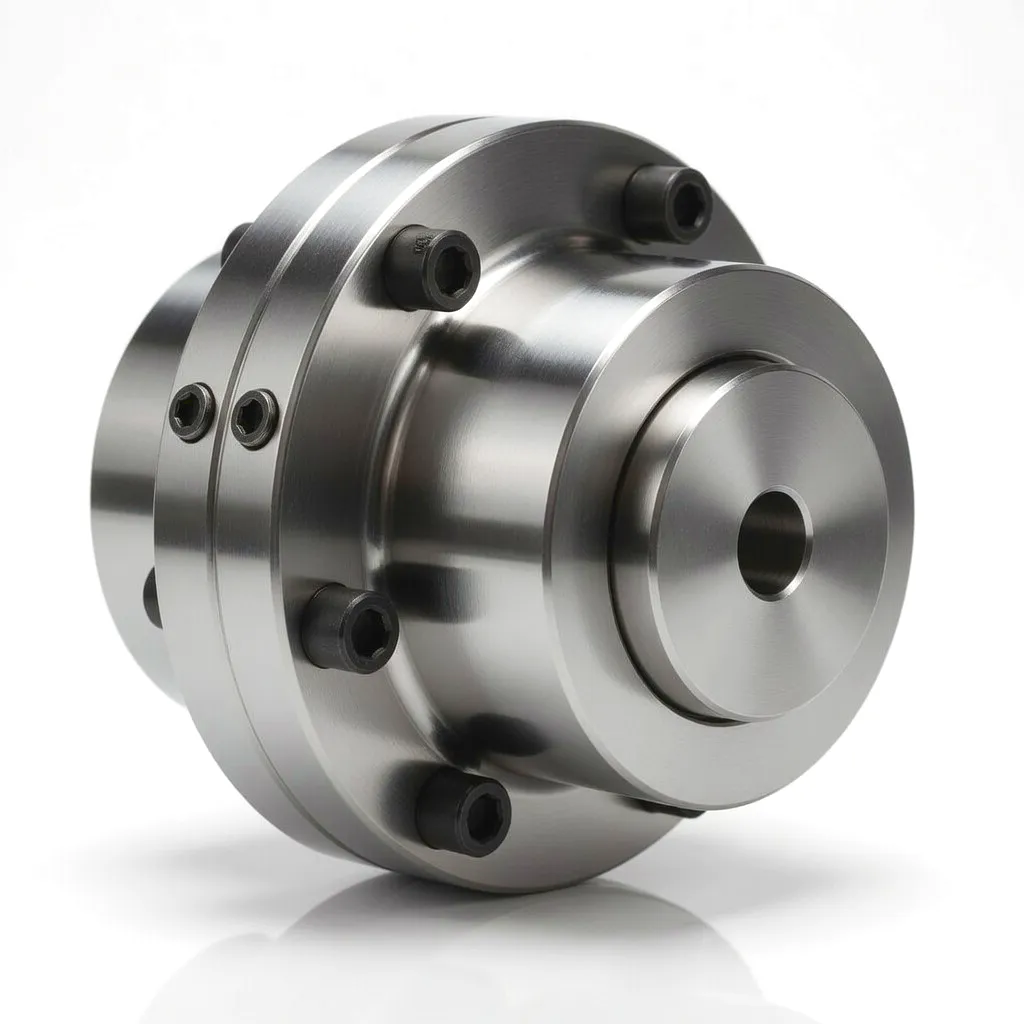
Ever Power gear type coupling product
Industrial gear coupling precision machined

Ready to Specify?

Talk to Ever Power’s Wind Coupling Engineering Team


Get a Quote →

édité par gzl