
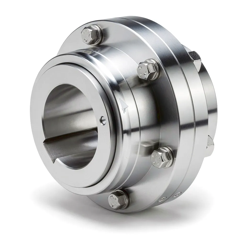
Working Principle: How Couplings Function in High-Speed Turbine Drives
At its core, a coupling in a thermal power application functions as a torque transmission bridge between two rotating shafts — the output shaft of the steam or gas turbine and the input shaft of the electrical generator. In a typical large UK combined cycle gas turbine (CCGT) plant, the turbine shaft rotates at 3,000 rpm to match the 50 Hz grid frequency directly, while in steam turbine installations, gearboxes may be interposed for intermediate speed reduction. In either case, the coupling must transmit the full rated torque reliably without introducing parasitic losses, vibration, or dynamic instability into either machine.
The dominant coupling type specified for this duty in the UK power sector is the gear coupling, though disc-pack and diaphragm couplings have gained significant market share in modern installations due to their oil-free maintenance profiles. A gear coupling achieves angular and axial misalignment compensation through the crowned tooth geometry of its gear mesh: the external teeth of the hub mesh with the internal teeth of the sleeve, and the crown profile of each external tooth permits small angular deflections without generating unacceptable tooth edge loading. This is precisely the mechanism that accommodates turbine shaft displacement caused by thermal growth during start-up and operation.
During a cold start — which is a routine event for peaking gas turbines at sites in the East Midlands that follow daily demand cycles — the turbine casing and shaft elongate by several millimetres relative to their cold positions as metal temperatures rise from ambient to operating levels above 500°C. Without misalignment-compensating capacity, this thermal expansion would impose severe bending loads on both machine bearing housings, accelerating wear and ultimately causing shaft seal failure. The coupling absorbs this differential movement silently, maintaining alignment within acceptable bearing load limits throughout the transient.
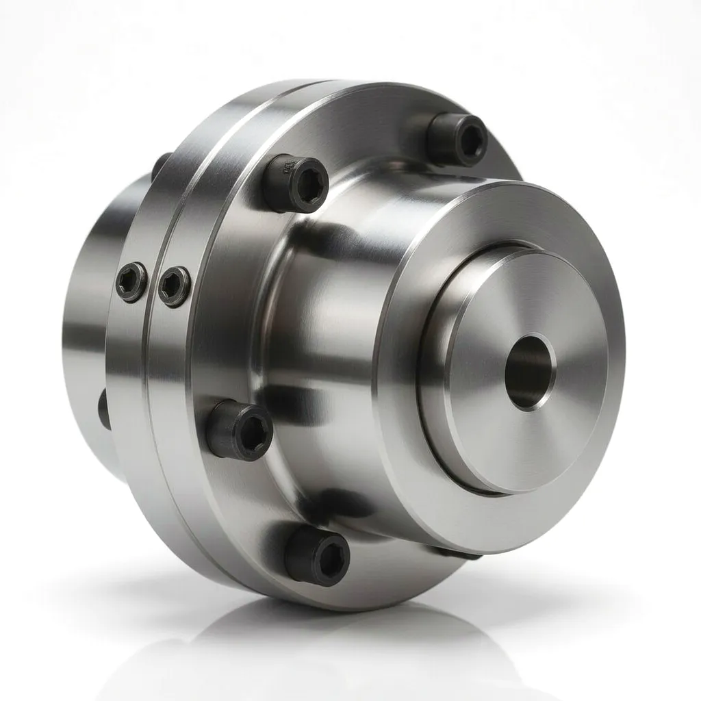
Key Functional Requirements
- Torsional stiffness within G2.5 dynamic balance spec
- Misalignment capacity ≥ 0.5° angular, ±3 mm axial
- Zero backlash during normal synchronous running
- Fail-safe under sudden load rejection events
- Compatible with oil mist or dry lubrication systems
- Full traceability to EN/BS material standards
Core Materials: Engineering Alloys for Extreme Duty in Power Station Environments
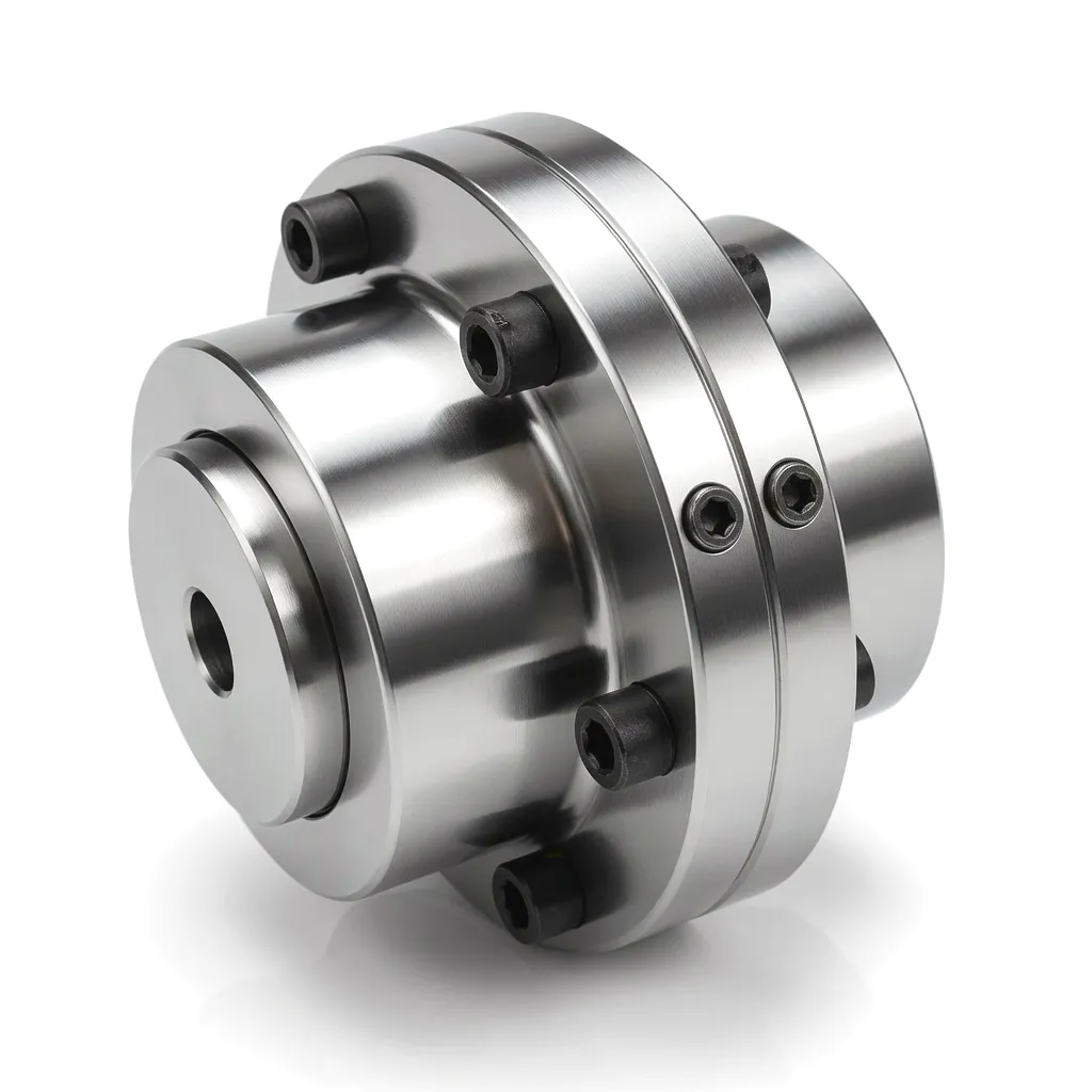
42CrMo4 मिश्र धातु इस्पात
Hub & sleeve forgings. UTS 900–1,100 MPa. Through-hardened 28–34 HRC. BS EN 10083 compliant.
Carburised Gear Surface
Tooth face hardness 58–62 HRC. Case depth 0.8–1.2 mm. Provides wear resistance in angular mesh motion.
17-4PH Stainless Steel
Disc-pack flex elements. Yield 1,000 MPa. Corrosion-resistant. Fatigue endurance for 10^8+ cycles.
40CrNiMoA Heat-Resistant Grade
High-temp flanges near turbine casings. Enhanced creep resistance up to 400°C service temperature.
Product Advantages: Why Power Station Engineers Specify These Couplings
Superior Misalignment Compensation
Gear and diaphragm couplings routinely accommodate angular misalignment of 0.5° to 1.5° and axial movement of ±3 to ±8 mm. In a 600 MW turbine unit at a station such as Cottam or West Burton, thermal growth of the turbine shaft between cold and hot conditions can reach 6–8 mm. Couplings with adequate axial float absorb this entirely without imposing thrust loads on generator or turbine bearings, extending bearing overhaul intervals significantly.
Outstanding Fatigue Life
The most demanding requirement in continuous baseload duty is cumulative fatigue endurance. Couplings specified for large generator drives are engineered to exceed 100,000 hours of service life — equivalent to over 11 years of around-the-clock operation — without requiring replacement of core components. Torsional fatigue analysis in accordance with ISO 10441 is conducted as part of the design validation, ensuring that tooth root stresses remain below the endurance limit under all load combinations.
Precision Dynamic Balance to G2.5
Rotating at 3,000 rpm in a 50 Hz synchronous machine, even modest residual unbalance in a coupling creates significant centrifugal forces that manifest as vibration measured on the machine casing. UK power station operators routinely specify G2.5 balancing grade in accordance with ISO 1940-1, requiring residual specific unbalance below 2.5 g·mm/kg. For very large generator couplings above 1,000 kg, this demands meticulous single-plane and two-plane balance correction after final assembly, performed on high-speed dynamic balancing machines.
Torsional Shock Absorption
Grid disturbances — including voltage dips, nearby fault clearances, and generator pole-slipping events — generate intense torsional transients in the rotor train. These transients, if unchecked, impose peak torques several times the rated value on coupling elements. Properly designed diaphragm and disc couplings integrate torsional compliance in their flex elements, limiting peak dynamic torque transmitted to the generator shaft and protecting against crankshaft-type fatigue cracking that has historically caused catastrophic failures in older installations.
Reduced Maintenance Burden
Modern disc and diaphragm coupling designs eliminate the lubrication requirement that has historically been the main maintenance task associated with gear couplings in UK power stations. Oil-lubricated gear couplings require annual oil changes plus periodic inspection of oil seals, whereas maintenance-free flex-element couplings need only visual inspection during planned outages. For UK generators operating under capacity market agreements where availability penalties are substantial, this reduction in scheduled maintenance events directly improves the annual availability factor and revenue performance.
Full Standards Compliance
Power station couplings supplied into the UK market are designed and manufactured in compliance with relevant international and British standards including ISO 10441 (flexible couplings for petroleum, chemical, and gas industry services), ISO 1940-1 (balancing quality), and EN 10083 (alloy steel specifications). Full documentation packages including design calculations, material certificates, inspection records, and dynamic balance reports are provided as standard, satisfying both the technical and audit requirements of UK power station operations teams.
Technical & Performance Parameters: Coupling Specifications for Thermal Power Generation
Application Scenario 13
Steam Turbine–Generator Drive in Thermal Power Generation Units
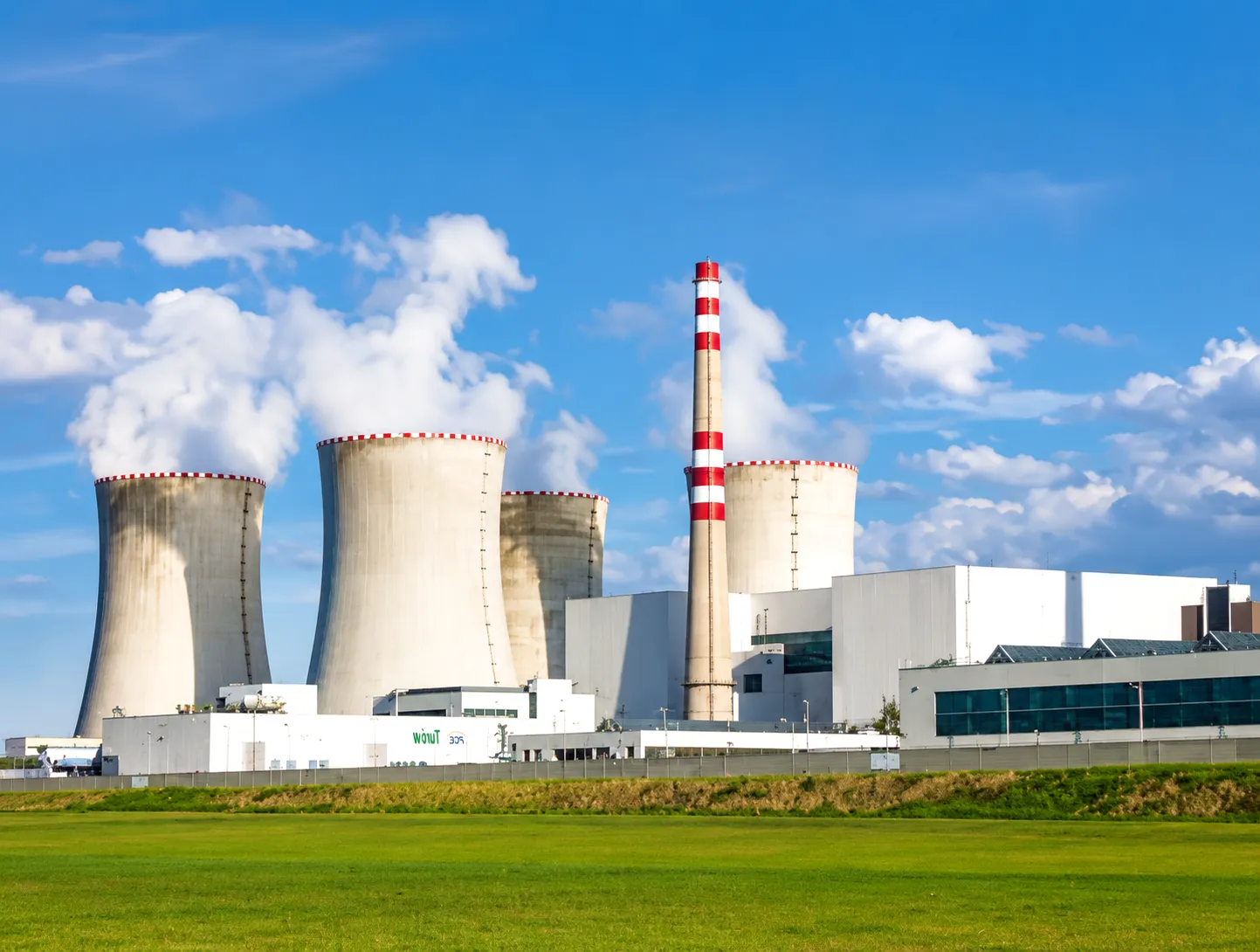
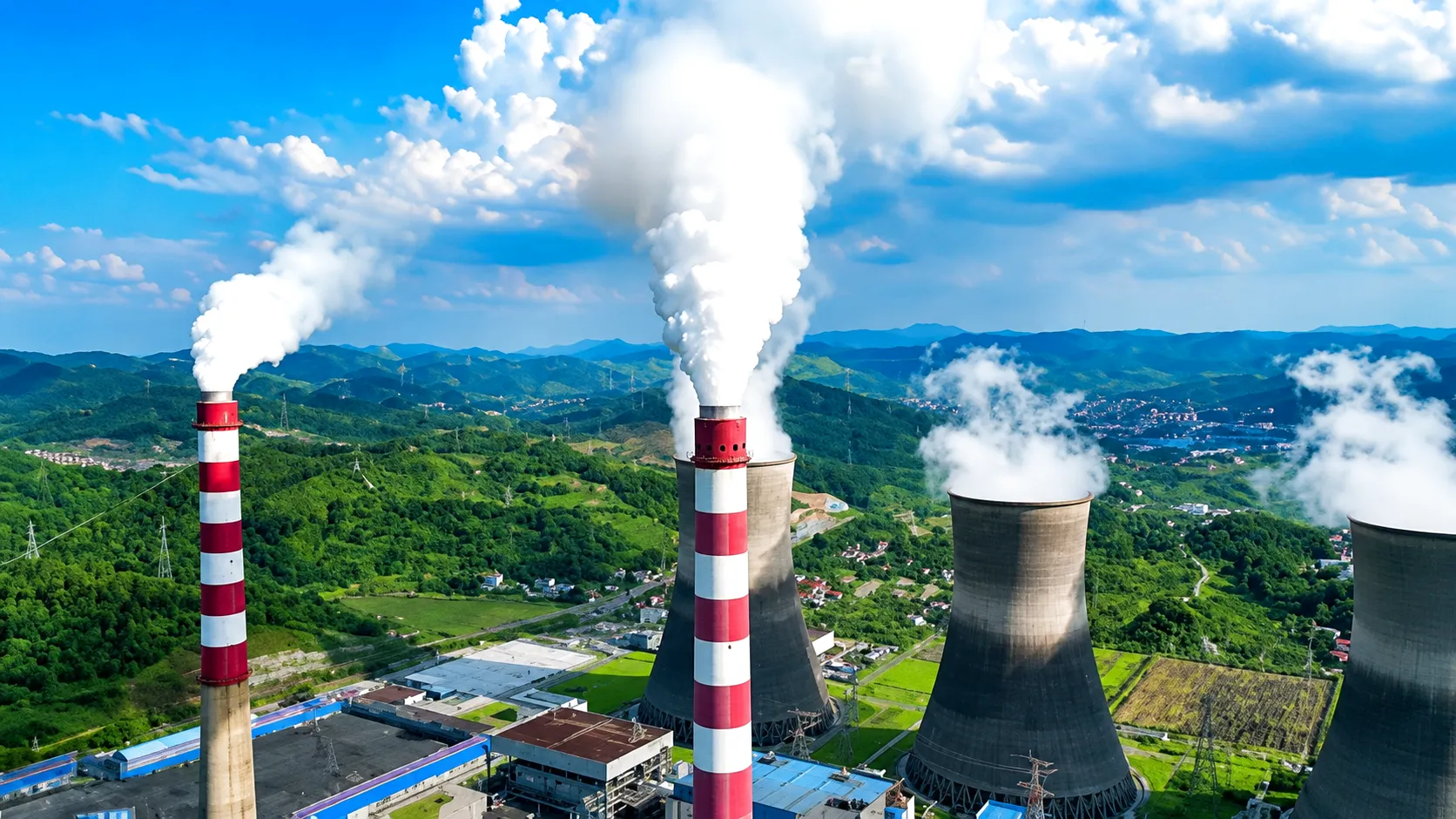
Operating Context — UK Thermal Fleet
Operating Speed
3,000 rpm
50 Hz synchronous UK grid
Peak Torque Range
1,000–2,500 kNm
400–660 MW unit class
Thermal Shaft Growth
6–8 mm
Cold to hot differential
Required Service Life
> 100,000 h
Continuous baseload duty
Further Industrial Application Scenarios: Coupling Performance Across Critical UK Industries
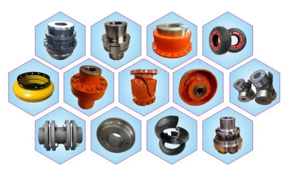
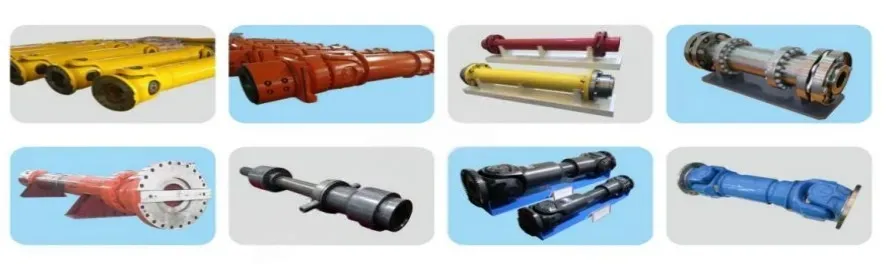
Our Coupling Product Range
Manufacturing Excellence
Ever Power: Precision Coupling Manufacturing & Customisation for the UK Power Sector
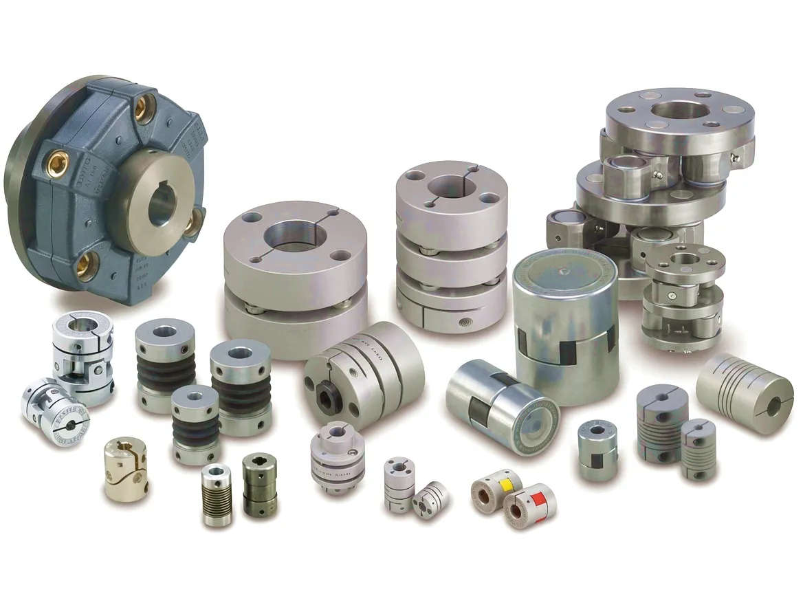
Ever Power operates a dedicated manufacturing facility equipped with advanced CNC turning, grinding, and gear cutting centres, producing couplings for the most demanding applications in thermal power generation, oil and gas processing, and heavy industry. Our in-house metallurgical capability allows us to procure, validate, and process alloy steel billets through the complete production chain — from raw material incoming inspection against EN 10083 material certificates, through forge quality control, heat treatment supervision, precision machining to ISO 286 tolerance grades, and final dynamic balancing on high-speed balancing machines calibrated to ISO 1940-1 standards.
Our customisation service is genuinely comprehensive. When a UK power station engineering team approaches Ever Power with a replacement coupling requirement for a turbine generator drive, our application engineering team begins with a detailed review of the existing shaft geometry, operating speed, torque envelope including peak load events, misalignment history from previous service records, and the maintenance interval philosophy of the plant operator. From this information, we develop a coupling design that may be a direct dimensional replacement for the existing component, or may incorporate engineering improvements — such as converting from a lubricated gear coupling to a maintenance-free disc pack configuration — that reduce the total cost of ownership over the remaining plant life.
Ever Power’s supply chain management ensures that critical deliveries to UK power stations — where planned outage windows are measured in days and delays carry significant financial penalties under availability contracts — are met reliably. We maintain strategic stocks of semi-finished coupling hubs in the most common diameter ranges, enabling rapid lead times for urgent replacement orders. Our documentation capability includes the full CMTR traceability package required by UK power generation operators, compiled into a single handover document set that satisfies both maintenance records and insurance inspection requirements.
🏠
In-House Forge & Machine
Complete vertical integration
📋
Full CMTR Documentation
BS EN 10083 material traceability
⚙
G2.5 Balance Certification
ISO 1940-1 compliant test reports
👥
Custom Bore & Keyway
To customer shaft drawings
Customer Success Story: Drax Group — North Yorkshire Biomass Station Coupling Upgrade
जगह
Selby, North Yorkshire
Sector
Biomass Power Generation
Unit Output
660 MW
चुनौती
Coupling Replacement

What Our Clients Say
★★★★★
“The disc coupling Ever Power supplied for our turbine–generator interface has delivered exactly what their application team promised — vibration levels have dropped significantly, and we’ve completely eliminated the annual coupling oil service that used to consume two man-days of outage time. The documentation pack was thorough and sailed through our QA audit.”
James H., Senior Mechanical Engineer
Biomass Power Station, North Yorkshire
★★★★★
“What sets Ever Power apart is their willingness to actually engage with the application before quoting a standard product. Their engineers understood the torsional implications of our cycling duty, and the coupling they designed reflected that understanding. We’re now three years and approximately 6,000 additional operating hours into the service life of this coupling without any issues whatsoever.”
Rachel T., Plant Engineering Manager
CCGT Power Station, East Midlands
★★★★★
“We had a tight outage window — 14 days for the full planned inspection — and Ever Power delivered the custom balanced coupling assembly within that schedule. The G2.5 balance certificate was included, and the unit returned to service with vibration readings that our monitoring system flagged as the lowest ever recorded on that bearing position. Genuinely impressive manufacturing quality.”
Michael D., Maintenance Contracts Director
Independent Power Producer, West Yorkshire
 Power Station Coupling Solutions Delivered On Schedule
अक्सर पूछे जाने वाले प्रश्नों
© Ever Power Industrial Couplings | gear-type-coupling.top | [email protected]
जीजेडएल द्वारा संपादित