
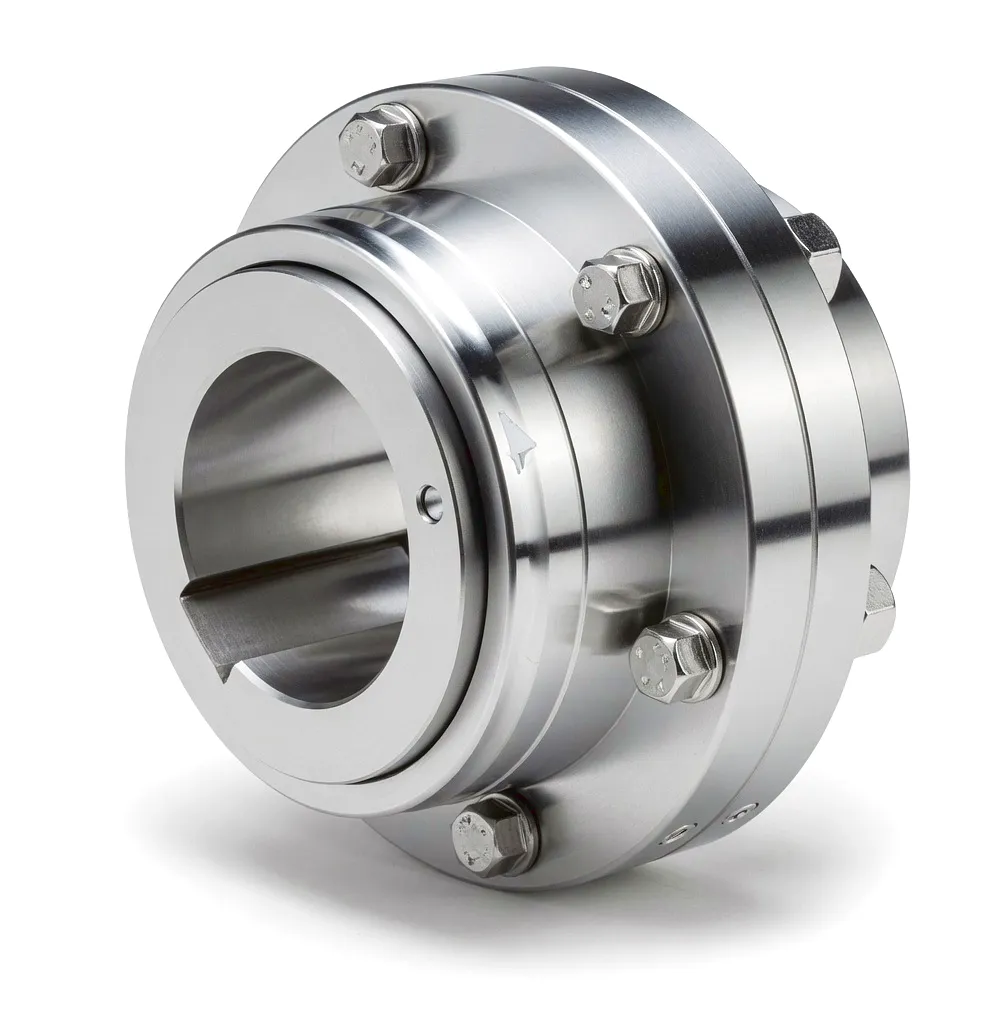
 Cement manufacturing is one of the most mechanically demanding industries on the planet. The sheer scale of rotating equipment — ball mills, vertical roller mills, roller presses — combined with the continuous, heavy-duty operating cycles means that every component in the drive train faces extraordinary punishment. Among those components, the coupling is arguably the most strategically critical yet chronically under-specified part of the entire system. A coupling failure in a cement mill does not simply mean a broken shaft; it means halted production lines, emergency maintenance callouts, costly spare parts logistics, and in many UK operations, contractual penalties for missed delivery commitments. Understanding precisely how couplings behave inside cement mill drive systems — and why gear-type couplings have become the preferred engineering choice for plant operators from Birmingham to Sheffield to the cement works of the Peak District — requires a close examination of the mechanical realities these machines face every single shift.
How Gear-Type Couplings Work in Cement Mill Drive Systems
작동 원리
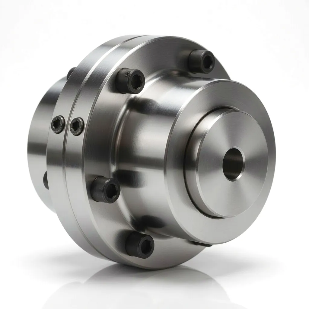 A gear-type coupling — often referred to as a gear coupling or toothed coupling — operates on the principle of meshing external and internal involute tooth profiles to transmit torque between two shaft ends. In a standard design, each shaft is fitted with an externally toothed hub, and a barrel-shaped sleeve with internal teeth engages both hubs simultaneously. Because the tooth geometry permits a small angular and parallel offset between the two engaged components, the coupling inherently accommodates shaft misalignment without generating destructive bending moments across the connected equipment.
In a cement ball mill drive train, this working principle is applied at several critical junctions. The electric motor output shaft connects to the input shaft of a reduction gearbox through a coupling; the gearbox output connects to the mill’s bull gear pinion shaft through a second coupling stage. At each junction, the coupling must transmit rated torques that can exceed 500,000 Nm on large installations while simultaneously absorbing the continuous angular wobble that develops as heavy foundations settle, thermal cycling causes shaft elongation, and bearing wear accumulates over months of operation. The gear-type coupling handles all of this through controlled lubricated tooth contact — when the tooth flanks slide slightly during each rotation to accommodate misalignment, they distribute the load smoothly rather than concentrating stress at a single point.
The lubrication film between meshing teeth serves a dual function: it reduces friction losses and carries away the heat generated during misalignment-induced sliding. In cement mill environments where ambient dust concentrations can reach tens of milligrams per cubic metre, the sealed housing of a properly specified gear coupling keeps abrasive cement particles from contaminating the lubrication space, preventing the accelerated gear tooth wear that would otherwise dramatically shorten service life. This sealed, lubricated tooth mesh is what distinguishes the gear coupling from open-type alternatives and makes it so well suited to the hostile interior of a cement plant.
Core Materials Used in Manufacturing High-Performance Couplings
Materials Engineering
Alloy Steel (42CrMo4 / 34CrNiMo6)
The standard material for gear coupling hubs and sleeves operating in cement mill duty. Heat-treated to achieve surface hardness of 55–62 HRC on tooth flanks while retaining a tough, ductile core. This combination resists pitting fatigue under the high Hertzian contact stresses that arise when full rated torque is transmitted through a small number of simultaneously loaded gear teeth.
Ductile Cast Iron (EN-GJS-600-3)
Used for the outer barrel sleeve and flange components in medium-duty cement auxiliary drive applications. Offers excellent vibration damping characteristics and is significantly less expensive to machine than alloy steel, making it suitable for applications where torque peaks are moderate and weight reduction is a secondary priority.
High-Performance Sealing Elastomers (NBR / FKM)
Nitrile rubber (NBR) seals are standard where lubricating grease compatibility is the primary concern. In cement mills where elevated temperatures near kiln-related hot zones occur, fluoroelastomer (FKM) seals rated to 200°C are specified. These materials keep lubricant inside and cement dust outside — a simple objective with profound consequences for coupling life expectancy in practice.
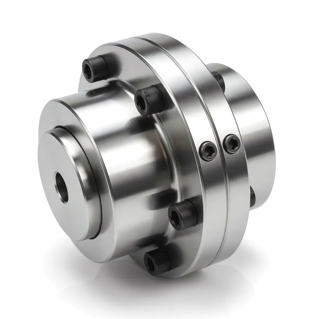 Beyond base materials, surface engineering plays an equally important role. Gear tooth flanks on cement mill duty couplings are routinely carburised and case-hardened to depths of 1.2–2.0 mm, producing a wear-resistant case whilst the underlying steel core retains sufficient toughness to withstand impact loads during mill start-up. Shot peening of the tooth root fillets is increasingly specified by leading UK cement plant engineering teams because it introduces compressive residual stresses that retard fatigue crack initiation — a detail that adds negligible manufacturing cost but extends tooth life by a statistically significant margin under the cyclic loading conditions of a ball mill drive.
Core Technical Advantages of Gear-Type Couplings for Cement Mill Drives
제품 장점
01
탁월한 토크 밀도
Gear couplings transmit higher torques per unit of outer diameter than virtually any other flexible coupling type. For cement ball mills where rated shaft torques routinely exceed 200,000 Nm and installation space is constrained by the mill flange geometry, this torque density advantage is not a marginal benefit — it is frequently the deciding factor that allows a gear coupling to fit where a jaw or disc coupling cannot.
02
Angular and Parallel Misalignment Tolerance
Standard gear couplings accommodate angular misalignment up to 1.5° per gear mesh and parallel offset of several millimetres depending on the bore size. In cement plant environments where vibrating foundations and thermally induced shaft movements are continuous realities, this misalignment capacity protects gearbox bearings and motor bearings from the additional radial and bending loads that a rigid connection would impose. UK plant engineers in Sheffield and Birmingham well understand the cost of premature bearing failure caused by coupling-transmitted misalignment forces.
03
High Overload and Shock Load Capacity
Ball mills create severe start-up shock loads as the stationary grinding charge is set in motion. Gear couplings rated to peak torque multiples of 2.0 to 3.5 times nominal absorb these transient events without the fatigue damage accumulation that flexible element couplings experience. The steel-on-steel tooth contact provides a positive torque path with no energy-absorbing element to degrade, which means the coupling’s shock load capacity does not diminish over years of service in the way that elastomeric couplings inevitably do.
04
Extended Maintenance Intervals
Cement plant scheduled maintenance shutdowns typically occur at annual or biennial intervals. A gear coupling with proper initial lubrication, correctly rated seals, and suitable grease selection can routinely operate through an entire annual campaign without intervention — sometimes extending to two years between regreasing in well-sealed designs. This low-maintenance characteristic aligns perfectly with the UK cement industry’s operational model, where unscheduled shutdowns carry a cost far exceeding the capital value of the coupling itself.
05
Dust and Contamination Resistance
The enclosed, sealed design of a correctly specified gear coupling prevents ingress of cement dust — a material with a Mohs hardness of approximately 6.0 — into the critical tooth mesh zone. Where open-type couplings or poorly sealed alternatives allow abrasive dust between meshing surfaces, wear rates accelerate exponentially and coupling failure becomes a matter of months rather than years. IP65-rated sealing arrangements are available as standard from quality manufacturers, meeting the protection requirements of most UK cement plant environments.
제품 기술 및 성능 매개변수
Specification Table
| 매개변수 | Typical Range | Cement Mill Duty Specification | 단위/표준 |
|---|---|---|---|
| 공칭 토크(Tn) | 500 – 4,000,000 | 100,000 – 2,500,000 | 뉴엠 |
| Peak Overload Torque | 1.5 – 3.5 × Tn | 2.0 – 3.0 × Tn (start-up) | Multiplier |
| 각도 불일치 | 0.5° – 1.5° | Up to 1.5° per mesh | Degrees |
| 평행 오프셋 | 0.1 – 5.0 mm | 0.5 – 3.0 mm | mm |
| Operating Speed (max) | 500 – 8,000 | 500 – 1,500 (mill side) | 회전수 |
| 허브 소재 | Steel, Alloy Steel, Cast Iron | 42CrMo4 / 34CrNiMo6 Alloy Steel | EN 10083 |
| 치아 표면 경도 | 50 – 64 HRC | 55 – 62 HRC (carburised) | HRC (Rockwell C) |
| Case Depth (carburising) | 0.8 – 2.5 mm | 1.2 – 2.0 mm | mm |
| 작동 온도 | -30°C to +200°C | -10°C to +120°C (ambient) | °C |
| Seal Protection Class | IP54 – IP65 | IP65 (dust-proof) | IEC 60529 |
| 윤활 유형 | 그리스/오일 | EP Semi-fluid Grease, NLGI 00/0 | DIN 51825 |
Industrial Application Scenarios: Where Couplings Perform in Cement Plants
응용 시나리오
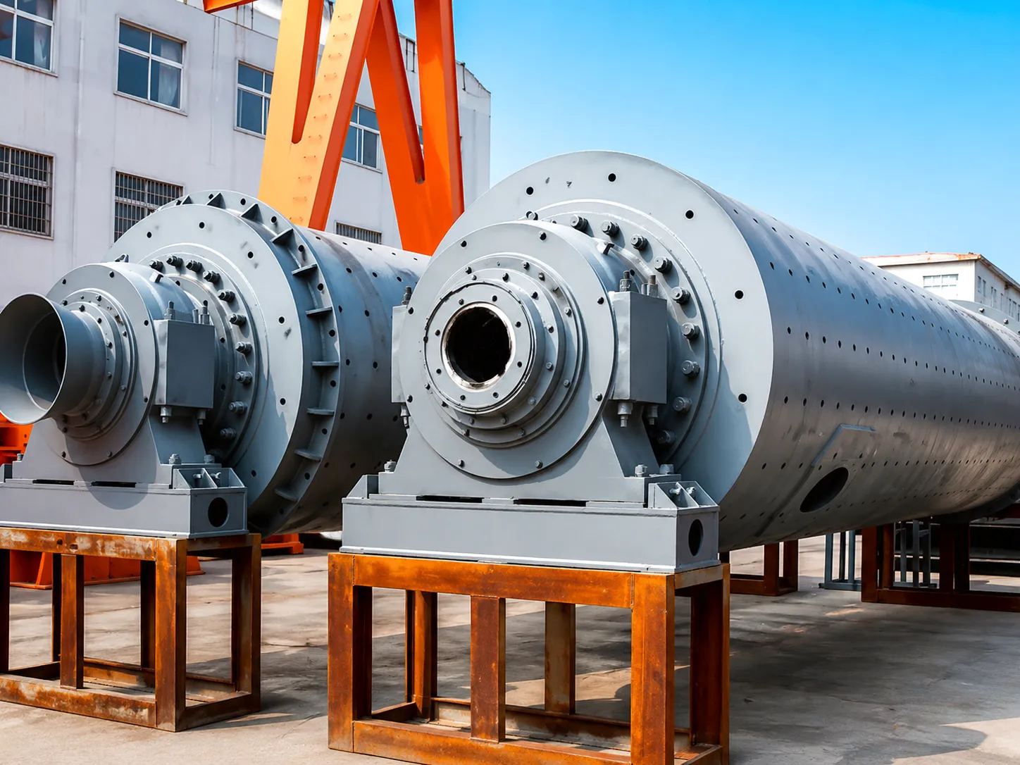
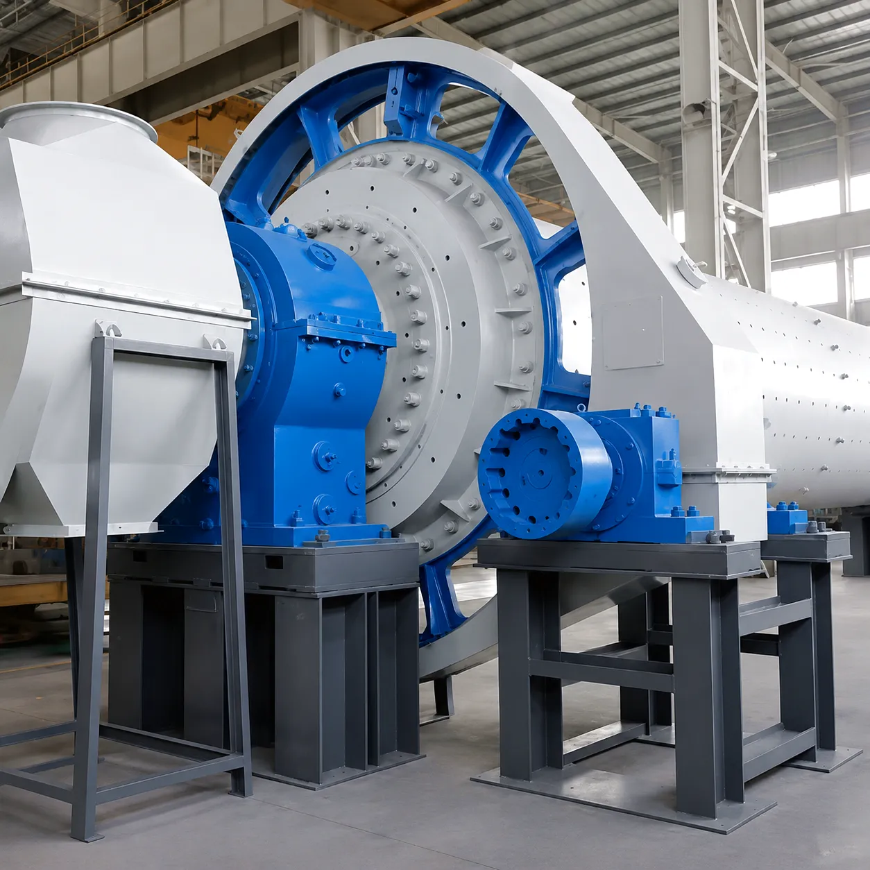 The ball mill main drive is the highest-stakes coupling application in a cement plant. Primary motors in the 1,000 kW to 6,000 kW range deliver power through a reduction gearbox to the mill pinion shaft, which meshes with a large open gear ring bolted to the mill barrel. The coupling at the motor-gearbox interface must handle full motor torque continuously whilst accommodating the slight angular misalignment that develops as the mill’s structural steel support frame flexes under thermal and dynamic loads over the course of a production campaign.
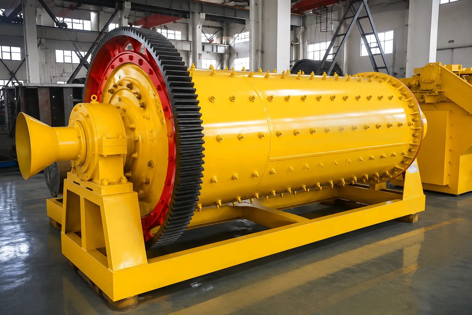
 Vertical roller mills represent the modern standard for raw material and cement grinding in new installations across the UK and Europe. Unlike ball mills, VRMs transmit drive torque downward through a vertical shaft arrangement, with the grinding table sitting directly on the gearbox output stage. The coupling between the electric motor and the VRM gearbox input operates in a vertical orientation and must accommodate not only the continuous rated torque but also the intermittent shock impulses generated as hard mineral fragments — flint nodules are a known challenge at several UK chalk quarry sites — pass through the grinding zone and create sudden load spikes.
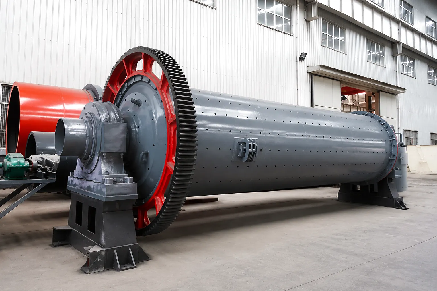
 Roller presses — also called high-pressure grinding rolls (HPGR) — are increasingly deployed ahead of ball mills in UK cement plants as a pre-grinding stage that reduces specific energy consumption. Each roller in an HPGR is driven by a dedicated motor and gearbox through a coupling, and the operating condition is characterised by high torque, moderate speed, and extremely high radial loading on the roller bearings from the interparticle compression forces. The coupling must therefore transmit rated torque whilst the connected gearbox output shaft deflects under radial bearing loads — a condition that generates a continuous angular misalignment at the coupling’s gear mesh that must be accommodated without generating excessive bending moments back into the gearbox output bearing.
 Beyond the main mill drives, cement plants contain numerous secondary power transmission applications where gear couplings provide valuable performance. Kiln auxiliary drives — used for slow rotation during maintenance and for controlled cooling after kiln shutdowns — operate at very low speeds with high intermittent torque loads, requiring couplings that remain reliable and lubricant-retentive even during infrequent use. Raw mill induced draught fans operating at flows of 200,000 to 600,000 m³/h are driven by motors in the 300 kW to 2,000 kW range through couplings that must handle the variable speed operation of variable frequency drives whilst remaining stable at all operating points across the speed range.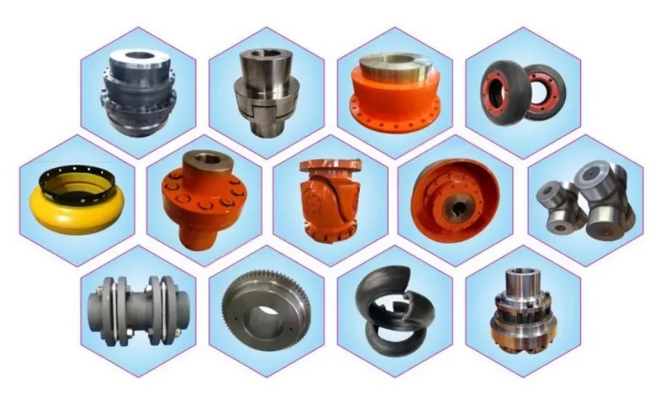
Ever Power industrial gear couplings — engineered for cement, mineral processing and heavy drive applications
Featured Coupling Products for Heavy Industrial Applications
Our Product Range
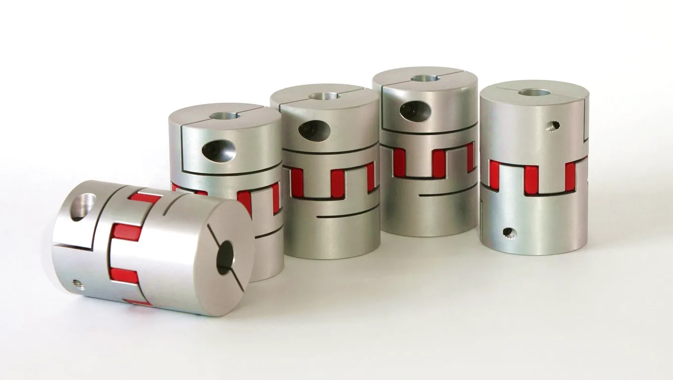
JSA 시리즈 스네이크 스프링 커플링
The JSA Series utilises a specially wound serpentine steel spring element that threads through alternating slots in two opposing flanges. This unique spring geometry delivers exceptional torsional flexibility, significantly damping shock loads and cyclic torque fluctuations that occur during ball mill start-up events. The design is particularly valued in applications where vibration isolation between driver and driven equipment is a priority alongside reliable torque transmission.
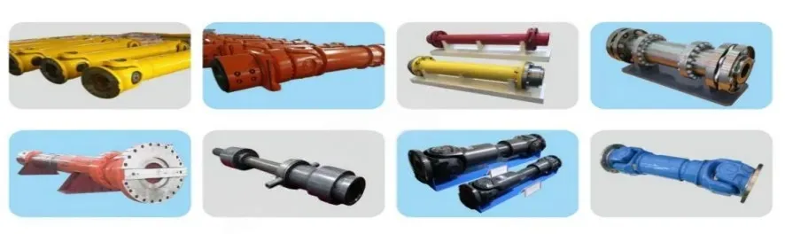
SWC 시리즈 범용 커플링
The SWC Series universal coupling is engineered for applications requiring large angular compensation between non-parallel shafts — a common challenge in cement plant auxiliary systems where drive components are offset by architectural constraints or where the driven shaft follows a non-horizontal path. With working angles up to 25° and robust Cardan cross-joint construction in alloyed steel, the SWC series provides reliable, long-service torque transmission across angular deviations that would be impossible to accommodate with conventional flexible couplings.
Customer Success Story: Birmingham Cement Group Eliminates Drive Failures with Gear Coupling Upgrade
Real-World Case Study · West Midlands, UK
2
Unplanned shutdowns per year (before)
0
Coupling-related shutdowns (18 months after)
£340K
Estimated annual downtime cost avoided
18개월
Maintenance-free operation achieved
A medium-scale cement production group operating a clinker grinding plant in the Birmingham area had been experiencing recurring failures on the main drive coupling of its 2,800 kW ball mill system over a three-year period. The original coupling — a rubber-element flexible coupling sourced from a general engineering supplier — was failing at the elastomeric insert approximately every 14 to 18 months, requiring emergency shutdowns during active production periods and incurring significant costs in emergency maintenance labour, crane hire for component access, and lost cement output. Each failure event took between 36 and 48 hours to resolve from detection to restart, during a period when UK construction activity meant that cement demand at the plant was consistently at peak levels.
The plant’s chief mechanical engineer engaged the Ever Power technical sales team following a recommendation from an industry contact at a Sheffield engineering consultancy. After reviewing the drive train specification — motor torque, gearbox ratio, mill inertia, direct-on-line start frequency and ambient dust concentration — the Ever Power engineering team identified that the original coupling had been undersized relative to the actual start-up torque the system generated, and that the elastomeric element’s hardness had been degrading progressively due to elevated ambient temperatures near the kiln preheater tower.
Ever Power supplied a custom-dimensioned gear-type coupling with a nominal torque rating of 680,000 Nm and a peak overload rating of 1,530,000 Nm, fitted with high-temperature FKM seals and pre-filled with an EP semi-fluid gear coupling grease specified for the site’s ambient temperature range. Installation was completed during a planned maintenance window with no extension to the scheduled downtime period. Over the subsequent 18 months of operation — encompassing two full winter production campaigns and one summer peak period — the coupling has required no maintenance intervention and no sign of wear was observed at an inspection conducted at the 12-month mark. The plant’s maintenance team has since engaged Ever Power for coupling reviews across three additional mill drives at the same facility.
★★★★★
“We had written off that mill drive as a chronic problem area. The Ever Power gear coupling changed that entirely. Eighteen months in, not a single unplanned stop attributable to the coupling — and the grease condition at the 12-month inspection looked almost new. The custom bore and keyway spec were machined exactly to our drawings.”
James R., Chief Mechanical Engineer
Cement grinding plant, West Midlands, UK
★★★★★
“The technical support from Ever Power before and during the coupling selection was as impressive as the product itself. They asked the right questions about our start-up frequency, our grease history, and our ambient conditions — questions that generic suppliers never think to raise. The coupling they specified handles our roller press drive without a vibration issue at any load point.”
Sarah T., Plant Maintenance Manager
Clinker production facility, Yorkshire, UK
★★★★★
“Delivery to our Sheffield site within the agreed lead time even though our order included non-standard bore sizes. The dimensional accuracy on the hubs was excellent — fitted straight to the gearbox shaft without any remedial machining needed on site, which matters when you are working within a tight planned maintenance window. We will be returning to Ever Power for our next procurement cycle.”
Mike H., Rotating Equipment Superintendent
Mineral processing & cement, Sheffield, UK
Frequently Asked Questions: Gear Couplings for Cement Mill Drive Systems
FAQ · UK Industry Focus
Ever Power Industrial Couplings
Ready to Solve Your Cement Mill Drive Challenge?
Our engineering team specialises in coupling solutions for cement, mineral processing and heavy industry across the UK and worldwide.
gzl님이 편집함