
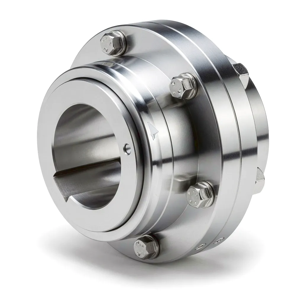
 Wind energy is no longer a peripheral ambition for the United Kingdom — it is a structural cornerstone of the national power grid. As turbine capacity scales upward and installation sites push further offshore into harsher environments, the mechanical components sitting between the rotor shaft and the gearbox face demands that would challenge almost any engineering solution. Gear type couplings have emerged as the preferred answer to those demands, combining robust torque transmission, angular misalignment tolerance, and extended service intervals within a compact, maintainable package. For turbine operators managing assets across Lincolnshire wind corridors or Scottish Highland ridgelines, the choice of coupling is not a procurement afterthought — it is a decision that directly shapes the availability factor and long-term cost profile of the entire installation.
How Gear Type Couplings Work Inside a Wind Turbine Drivetrain
Gear Tooth Engagement Mechanism
At the core of a gear type coupling are two hubs, each machined with external gear teeth, and a sleeve — or outer ring — carrying matching internal teeth. The hub teeth are typically crowned, meaning they are slightly convex along their length. This crowning is not cosmetic: it permits the hub to pivot within the sleeve by small angular amounts without inducing edge loading on the tooth flanks. In a wind turbine, the rotor shaft and the gearbox input shaft are rarely in perfect alignment due to manufacturing tolerances, thermal growth, and dynamic deflection under load. The crowned tooth geometry absorbs these misalignments continuously during operation, transmitting torque smoothly without binding or generating harmful bending moments.
Lubrication and Load Distribution
Lubrication is the operating medium of a gear type coupling: without it, tooth-on-tooth contact would rapidly destroy the precision surfaces. Grease-lubricated designs dominate wind turbine applications because grease is retained within the sealed sleeve more reliably than oil, especially in the vertically inclined nacelle environment at altitude. The grease fills the tooth gap and the internal void of the sleeve, reducing friction, carrying away heat, and preventing moisture ingress — the last point being particularly significant for turbines operating along the exposed North Sea coastline or in the rain-exposed environments of the Welsh uplands. Sealed end covers on both sides of the sleeve maintain this lubrication charge across service intervals that can span two or more years, critically reducing the need for technicians to perform nacelle-level maintenance tasks.
Torque Transmission and Dynamic Balancing
Wind turbines operate across a wide speed and torque band. A 3 MW turbine, for example, might see rotor shaft speeds ranging from 6 to 18 rpm, with peak torques exceeding 1,800 kNm during high-wind-speed operation. Gear type couplings in this position are engineered to transmit these extreme torques with mechanical efficiencies typically above 99.8%, because any power lost in the coupling translates directly to reduced electrical output. The multi-tooth engagement distributes the load across a large contact surface, keeping individual tooth stresses well within fatigue limits even across the multi-decade service life expected of modern turbines. Finished assemblies are dynamically balanced to fine tolerance grades, eliminating the vibration imbalances that would otherwise excite resonance in the drivetrain structure at rotational frequencies.
Core Materials Behind Wind-Grade Gear Type Couplings
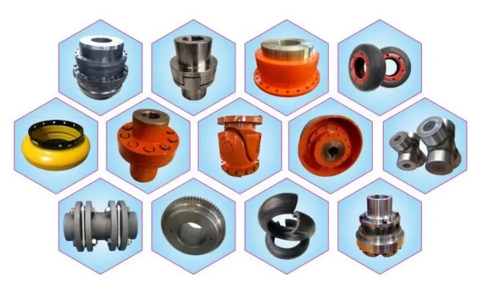
Material selection governs fatigue resistance, corrosion tolerance, weight, and weldability — all critical parameters in nacelle-mounted coupling assemblies.
Hub Material
Alloy Steel 42CrMo4
Chrome-molybdenum alloy steel heat-treated to achieve tensile strengths of 900–1100 MPa. The alloying elements produce a through-hardened microstructure that resists the rolling-contact fatigue damage that develops on coupling teeth after millions of load cycles. Widely used across the European drivetrain industry, it is specified in DIN 17200 and performs reliably across temperature ranges from -40 °C to +120 °C — encompassing the extremes seen at North Sea offshore installations.
Sleeve Material
Carburised Low-Alloy Steel
The outer sleeve bears internal tooth loads and must combine high surface hardness with a tough core to resist impact. Carburising raises surface carbon content, allowing case hardening to 58–62 HRC at the tooth flanks while retaining a core hardness of 30–36 HRC. This dual-zone hardness profile is particularly effective in wind turbine applications where shock torque events — caused by sudden gust loading or emergency braking — could fracture a uniformly hard sleeve but are safely absorbed by a carburised component.
การบำบัดพื้นผิว
Zinc Phosphate + Epoxy Coating
Offshore and coastal turbines in the UK face severe salt spray, condensation, and UV exposure that degrade unprotected steel rapidly. A zinc phosphate conversion coating applied before epoxy painting provides two layers of corrosion protection: the phosphate layer promotes adhesion and offers early sacrificial protection, while the epoxy topcoat creates a barrier against moisture and chloride ingress. This treatment system is routinely tested to 1,500+ hours of salt spray per ISO 9227, aligning with the requirements of offshore certification bodies including DNV GL and Lloyd’s Register.
Sealing System
FKM Fluoroelastomer Seals
Fluorocarbon (FKM) elastomers maintain their mechanical properties across extreme temperature cycles and resist degradation from the specialised coupling greases used in wind turbine environments. Unlike standard NBR seals that can swell or harden when in contact with synthetic lubricants, FKM seals retain sealing lip contact force throughout service intervals exceeding 20,000 operating hours. This long-interval sealing capability is critical for offshore turbines where replacement seal maintenance requires expensive marine access operations.
Technical Advantages Specific to Wind Energy Deployment
✓ High Misalignment Tolerance
Angular misalignments up to 1.5° and parallel offsets in the range of 0.3–1.5 mm are accommodated continuously without inducing bearing overloads. Wind turbine main shafts experience dynamic misalignment as rotor loads change with wind direction and speed — a gear type coupling absorbs these variations silently, protecting both the main bearing and the gearbox input stage from fatigue damage that would otherwise develop over years of operation. This characteristic alone can extend drivetrain overhaul intervals by two to three years in high-utilisation turbines.
✓ Compact Power Density
The gear tooth engagement transmits higher torque per unit mass than disc, jaw, or elastomeric coupling alternatives of equivalent external dimensions. In a wind turbine nacelle where every kilogram of rotating mass adds cost to the tower structure and foundation, this power density advantage is commercially significant. Nacelle weight reduction programmes pursued by leading OEMs — including those operating manufacturing facilities in the Sheffield and Rotherham advanced manufacturing corridor — have specifically highlighted gear coupling substitution as a route to mass savings in the drivetrain assembly.
✓ Extended Service Life
Properly specified and lubricated gear type couplings in wind turbine service regularly achieve 15–20 years of operation without tooth replacement, provided that regular condition monitoring confirms the grease state remains within specification. This longevity is a function of the combination of hardened tooth surfaces, retained lubrication, and effective sealing — and it aligns well with the 20–25 year design life specified for modern turbines under IEC 61400-1. For operators managing portfolios of turbines across Scottish wind farms, a coupling that matches the turbine service life eliminates what would otherwise be a scheduled drivetrain replacement event.
✓ Shock Load Absorption
Grid fault events and emergency brake applications generate impulsive torque spikes that can reach three to five times the rated operating torque in fractions of a second. The gear contact area in a gear type coupling acts as a distributed compliance mechanism: the tooth flanks deflect elastically under these spikes, absorbing the impulse energy and attenuating the shock wave before it propagates into the gearbox. This protective function reduces the incidence of gearbox planet carrier cracking and ring gear damage that is statistically one of the most expensive failure modes in utility-scale wind turbine operations.
✓ Low Noise and Vibration Signature
Wind turbines situated near residential areas — increasingly common as planning consent is sought for onshore sites in England and Wales — must meet noise emission limits set by the Institute of Acoustics’ ETSU-R-97 methodology. Gear type couplings, with their multi-tooth engagement and grease damping, generate measurably lower transmitted vibration to the nacelle structure than chain or rigid flange alternatives. Lower structural vibration means reduced acoustic radiation from nacelle panels and tower skin, helping turbine operators maintain compliance with planning condition limits without resorting to operational curtailment or costly acoustic insulation retrofit work.
✓ Ease of Assembly and Replacement
Split-sleeve gear coupling designs allow the outer sleeve to be removed radially without disconnecting the shaft pair, which is invaluable at nacelle height where axial shaft movement is constrained by adjacent components. This feature reduces planned maintenance time significantly compared to solid-sleeve or disc coupling alternatives that require shaft separation before the coupling element can be withdrawn. For operations teams managing assets in remote locations such as the Pennine moorlands or the Aberdeenshire coast, reduced maintenance duration translates directly to improved turbine availability and lower crane hire cost per service visit.
Product Technical Performance Parameters
The table below reflects typical specification ranges for wind-turbine-grade gear type couplings used across main shaft, gearbox, and generator interfaces. Custom configurations beyond these ranges are available from Ever Power — contact our technical sales team to discuss your specific application parameters.
| พารามิเตอร์ | Typical Range | หน่วย | Notes |
|---|---|---|---|
| Nominal Torque (Tn) | 500 – 2,500,000 | Nm | Covers pitch drive to main shaft positions |
| ความสามารถในการรับแรงบิดสูงสุด | Up to 3× Tn (shock) | Nm | Emergency brake and grid fault events |
| การเยื้องศูนย์เชิงมุม | 0° 30′ – 1° 30′ | Degree | Crowned tooth geometry enables continuous operation |
| Parallel Offset Tolerance | 0.3 – 1.5 | มม. | Size-dependent; verified per ISO 14691 |
| Axial Displacement | ±2 – ±12 | มม. | Thermal expansion compensation function |
| Rotational Speed | 6 – 1800 | รอบต่อนาที | Rotor shaft to generator shaft applications |
| Hub Material | 42CrMo4 / 34CrNiMo6 | — | Heat treated, 900–1100 MPa tensile strength |
| Tooth Surface Hardness | 58 – 62 | HRC | Case carburised + quenched and tempered |
| Operating Temperature | -40 – +120 | °C | Compatible with Arctic-grade wind turbine specs |
| Mechanical Efficiency | > 99.8 | % | At rated torque, well-lubricated condition |
| Balance Grade | G6.3 / G2.5 (custom) | ISO 1940-1 | G2.5 available for generator-side positions |
| Corrosion Protection | Zn-phosphate + Epoxy | — | 1500 h salt spray per ISO 9227 (C5-M marine) |
| Service Interval | 20,000 – 40,000 | Hours | Condition monitoring recommended beyond 20,000 h |
Wind Turbine Application Scenarios: Where Gear Type Couplings Perform
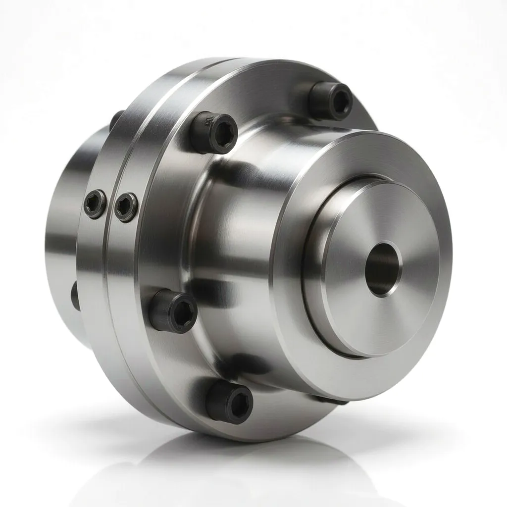 The main shaft position is the highest-torque mechanical interface in a wind turbine, bearing loads generated directly by the rotor in response to wind pressure on the blades. For a 2 MW turbine operating at an average wind speed of 8 m/s, steady-state torques at this shaft position commonly exceed 1,000 kNm, with peak values during gusts or emergency stops considerably higher. Gear type couplings specified for this position are engineered to ISO 14691 and must pass fatigue testing at three times rated torque for a prescribed number of cycles before approval for turbine installation.
 Between the gearbox output shaft and the generator input, coupling requirements shift: torques are lower but rotational speeds are much higher — typically 1,200–1,800 rpm in conventional synchronous and asynchronous generators. At these speeds, dynamic balancing becomes critical, because any residual imbalance generates forces that grow with the square of rotational speed. An unbalanced coupling operating at 1,500 rpm creates four times the vibration force of the same imbalance at 750 rpm. For offshore turbines in the Hornsea, Dogger Bank, or East Anglia Array developments off the East Yorkshire and Suffolk coasts, where nacelle access requires specialised marine vessels at significant day-rate cost, any vibration-induced bearing failure in the generator system translates to an expensive and weather-dependent corrective maintenance campaign.
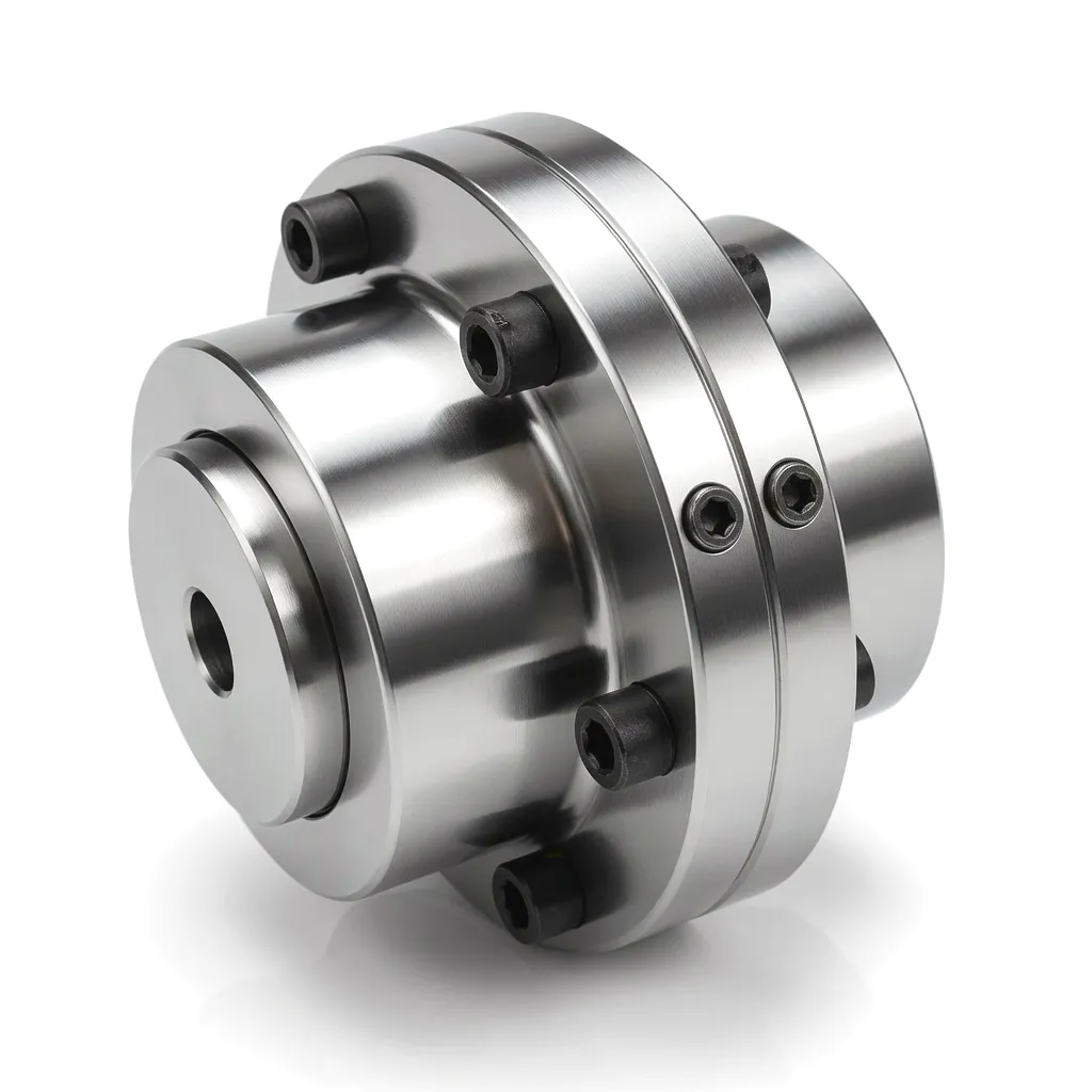 Modern variable-speed, variable-pitch turbines rely on continuous servo-actuated blade pitch adjustment to regulate rotor speed and power capture across wind speeds from cut-in (approximately 3 m/s) through rated (approximately 12 m/s) to cut-out (typically 25 m/s). Each blade is driven by an independent pitch drive comprising an electric motor, a planetary gearbox, and a pinion engaging the blade root ring gear — and within this drive chain, a gear type coupling connects the motor output shaft to the gearbox input. The compactness of the pitch gearbox housing inside the blade root hub places severe dimensional restrictions on the coupling, while the application demands reliable emergency pitch-to-feather capability within seconds during overspeed events.
 A significant portion of the UK’s onshore wind fleet was installed between 1995 and 2010 and now approaches or exceeds the end of its original design life. The repowering and life-extension programmes being carried out on these assets — many of them clustered in Scotland, Wales, and the South West — provide an important market for coupling upgrades. Older turbines often carry first-generation disc or elastomeric couplings whose degraded flexibility elements require replacement every three to five years, creating recurring maintenance events that add operational cost and absorb engineering resource. Retrofitting with modern sealed gear type couplings offers these older assets a 15-year service interval and reduced drivetrain vibration that can help satisfy the stricter noise compliance assessments typically required when life-extension planning applications are submitted.
 Before a new turbine model or gearbox design enters commercial production, it must be validated on a closed-loop nacelle test rig that can apply representative load spectra under controlled laboratory conditions. The Offshore Renewable Energy (ORE) Catapult facility in Glasgow and the National Renewable Energy Centre (Narec) site in Blyth, Northumberland, represent the UK’s leading infrastructure for this work. Both facilities use gear type couplings extensively in their test rig drivetrains because the couplings’ ability to accommodate the controlled misalignments inherent in any multi-machine test bench — while transmitting both the driving and braking torques applied by back-to-back motors — makes them technically superior to rigid flanged connections that would require exceptional alignment precision and generate uncontrolled bending loads on the test specimens.
Manufacturing Partner
Ever Power: Precision Manufacturing for Wind Energy Gear Couplings
Ever Power operates precision manufacturing facilities equipped with CNC gear hobbing, grinding, and heat treatment lines capable of producing gear type couplings from the smallest pitch drive frame sizes up to the largest main shaft configurations used in 5+ MW utility turbines. Every component passes through a documented quality process that includes incoming material certification review, dimensional inspection at critical stages using CMM measurement, tooth profile analysis on Klingelnberg gear inspection equipment, and final dynamic balancing on purpose-built balancing mandrels traceable to national standards.
The Ever Power customisation capability extends beyond standard catalogue sizes. The engineering team works directly with client design engineers to develop application-specific coupling configurations: non-standard bore dimensions and keyway configurations matched to existing shaft drawings; modified flange bolt patterns aligned to gearbox or generator interface dimensions; split-sleeve designs engineered for installations with restricted axial access; and special coating systems qualified for the C5-M marine corrosion environment of North Sea offshore turbines. This depth of customisation, backed by a rapid prototyping workflow and a vertically integrated supply chain, makes Ever Power a practical choice for both new turbine OEM programmes and retrofit projects across the UK wind sector.
Ever Power’s supply chain infrastructure maintains strategic material stock and semi-finished coupling blanks, enabling accelerated delivery programmes for emergency replacement requirements. Shipping to UK distribution hubs in Birmingham, Manchester, and Aberdeen is managed through established freight partnerships with transit times that support typical turbine maintenance scheduling windows. Full traceability documentation — material certificates, heat treatment records, inspection reports, and balancing certificates — is supplied with each shipment in formats compatible with the quality management system requirements of major UK wind turbine operators.
⚙
CNC Gear Grinding
ISO 1328 accuracy grade 5 and above for critical wind applications
📈
CMM Inspection
100% dimensional verification on all wind-sector deliveries
🔥
การอบชุบด้วยความร้อน
Carburising, quench and temper — in-house with furnace certification
⚖
Dynamic Balancing
G2.5 balancing achievable for high-speed generator positions
🕑
6–8 Week Delivery
Custom production timelines to UK wind sector maintenance schedules
Related Drive Components from Ever Power
Wind turbine drivetrains require more than couplings alone. Ever Power supplies complementary gearbox solutions that integrate with our gear type couplings to provide complete drivetrain packages for turbine OEM and retrofit projects.
PTO Gearbox
A heavy-duty PTO gearbox designed for high-torque auxiliary drive applications, with robust cast housing and precision helical gear sets. Pairs effectively with gear type couplings in wind turbine auxiliary drive systems including cooling fan and hydraulic pump drives, where compact dimensions and reliable power transmission are required in the constrained nacelle environment.
PTO Gearbox
The HC-RC30-193 offers a stepped ratio configuration suited to applications requiring intermediate output speed adjustment between the primary drivetrain and auxiliary subsystems. Its machined mounting flange interfaces with standard gear type coupling hubs, allowing straightforward integration into drivetrains where space constraints and specific reduction ratios demand a purpose-engineered gearbox solution rather than an off-the-shelf catalogue item.
Customer Success: Sheffield Advanced Manufacturing — Wind Component Testing Division
ที่ตั้ง
Sheffield, South Yorkshire
Sector
Wind Turbine Drivetrain Testing
ท้าทาย
Frequent Coupling Replacement on Test Rigs
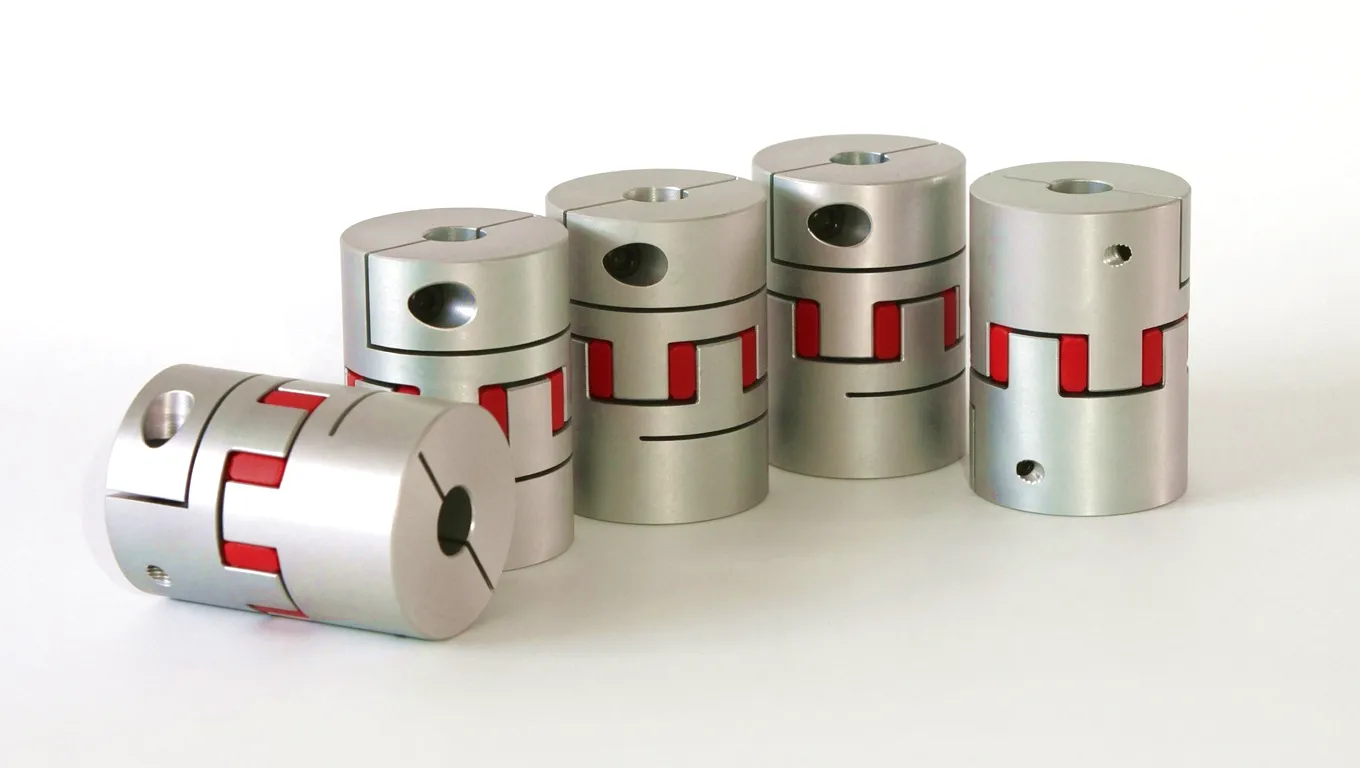
A component testing facility operating within Sheffield’s Advanced Manufacturing Park — one of Europe’s leading clusters for precision engineering and wind energy component development — was running a back-to-back drivetrain test bench that replicated the torque loading profiles seen on 2.5 MW turbine main shaft assemblies. The facility’s existing elastomeric couplings were requiring replacement every fourteen months on average, due to degradation of the rubber elements under the combined effects of cyclical torque reversals during bidirectional test sequences and the elevated temperatures generated by the test bench’s enclosed housing. Each replacement event took the test bench offline for three working days and consumed significant technician time.
The facility’s lead drivetrain engineer contacted Ever Power following a recommendation from a colleague at a neighbouring turbine OEM operation in Rotherham. After a detailed technical review of the test bench operating cycle — including torque reversal frequency, peak torque values, and thermal environment — Ever Power’s engineering team proposed a sealed gear type coupling in 42CrMo4 with a balanced service factor of 2.2 relative to the peak test torque, FKM seals for the high-temperature environment, and a split-sleeve design that would allow future element replacement without shaft disconnection.
The custom coupling was delivered to the Sheffield facility within seven weeks of order confirmation. Following installation and commissioning, the test bench has now operated for 26 months without any coupling-related maintenance intervention. The facility has since placed orders for two additional Ever Power gear type couplings for a second test bench being commissioned for 3.6 MW gearbox validation work, with delivery coordinated to align with the facility’s planned commissioning schedule. The original test bench downtime saving has been calculated at approximately 14 working days over the 26-month period compared to the previous maintenance pattern.
“The Ever Power gear coupling has now outrun every elastomeric coupling we tried in this application. Twenty-six months with zero maintenance events on a bench that previously consumed couplings annually. The engineering support during specification was thorough and technically credible — they understood the accelerated life test loading profile and sized the coupling accordingly rather than just offering a standard catalogue item.”
— Lead Drivetrain Engineer, Wind Component Testing Facility, Sheffield Advanced Manufacturing Park
“We specified Ever Power couplings for the retrofit programme on our ageing turbine fleet in the East Midlands. The split-sleeve design was particularly important — our technicians could complete the coupling change without a full shaft disconnection, which saved approximately two days of crane time per turbine. The traceability documentation supplied with each coupling meets our ISO 9001 audit requirements without any additional processing on our side.”
— Operations Director, Wind Farm Asset Management Company, Nottingham
“The offshore corrosion specification on the couplings we ordered from Ever Power has performed exactly as stated. We installed them on two turbines at an East Yorkshire offshore site eighteen months ago and the first visual inspection during a scheduled service showed the coating system in excellent condition with no signs of degradation. The FKM seal retention of grease at an offshore site was a particular concern before we placed the order — the technical datasheet and the follow-up test report from Ever Power gave us the confidence we needed.”
— Procurement Manager, Offshore Wind O&M Contractor, Hull, East Yorkshire
คำถามที่พบบ่อย
Common questions from wind turbine engineers, procurement teams, and asset managers across the UK renewable energy sector.
Ready to Specify Wind-Grade Gear Type Couplings?
Send Ever Power your application data — shaft diameters, rated torque, turbine model — and receive a formal technical proposal and competitive pricing within 48 hours.
Or email directly: [email protected]
แก้ไขโดย gzl