
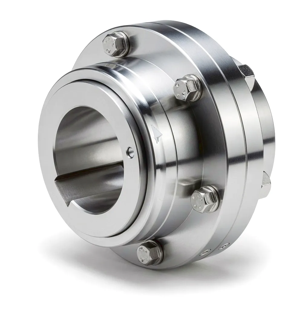
At the heart of every thermal power station, a precise mechanical handshake takes place between turbine and generator. The coupling — often underestimated in public discourse yet absolutely critical in engineering practice — bears the full burden of transmitting hundreds of megawatts of rotational energy without losing a single watt to vibration, misalignment, or fatigue failure. In the United Kingdom, where ageing coal-fired stations are being modernised and gas-fired combined-cycle plants continue to expand output capacity, the specification of the correct coupling type can be the deciding factor between planned uptime and catastrophic unplanned shutdown. Steam turbines driving large generators operate at rotational speeds of 3,000 rpm (for 50 Hz grid synchronisation), presenting a demanding combination of high speed, variable thermal loading, and continuous cyclic torque that no coupling designer can afford to underestimate. Gear-type couplings and disc couplings have established themselves as the benchmark choices for these environments, offering angular and axial compensation capabilities that absorb thermal expansion of turbine shafts while maintaining the dynamic balance precision required for smooth, vibration-free power delivery. Understanding why these products are chosen — and what separates a well-engineered coupling from an inadequate one — is essential reading for any UK power station engineer, procurement manager, or OEM turbine supplier.
Thermal Power Generation: Steam Turbine-to-Generator Drive Coupling
The Scale of the Challenge
Large UK coal and gas power units routinely generate 300 MW to 660 MW from a single turbine shaft. The coupling connecting the last low-pressure turbine stage to the generator rotor must transmit peak torques reaching hundreds of kiloNewton-metres — values that would destroy an under-specified component within hours of commissioning. At 3,000 rpm, even a 0.05 mm eccentricity in coupling alignment translates into vibration amplitudes that can strip babbitt from journal bearings and propagate fatigue cracks through turbine casing bolts. The engineering margin for error is essentially zero, which is why power station engineers across Birmingham, Sheffield, and the East Midlands energy corridor routinely specify purpose-designed, dynamically balanced coupling assemblies that meet or exceed ISO 1940-1 G2.5 balance grade requirements.
Thermal Expansion: The Hidden Misalignment Driver
When a steam turbine transitions from cold-standby to full-load operation, the turbine casing, shaft, and pedestal bearings all expand at different rates depending on material properties and temperature gradients. In a typical 500 MW set, the turbine shaft can shift axially by 30–50 mm and deflect angularly by fractions of a degree that — while geometrically small — impose very significant bending moments at the coupling interface. A rigid coupling in this position would transmit all that bending energy directly into the generator rotor, stressing the shaft journal and potentially destabilising the rotor’s critical speed map. Flexible gear-type couplings are therefore the dominant choice for this application: their crowned gear tooth profiles accommodate both angular misalignment (typically ±0.5°) and axial displacement, converting what would otherwise be destructive bending forces into managed sliding friction within the coupling’s lubricated sleeve. This is not a compromise solution — it is the engineered optimum for continuous-duty power generation.
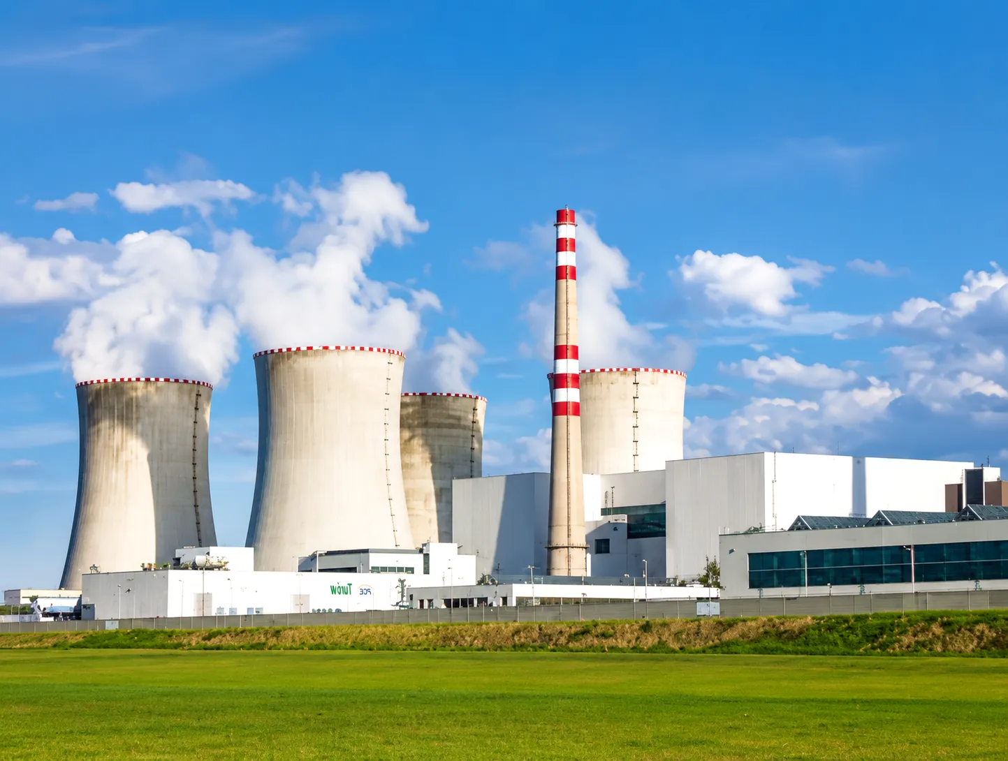 The thermal expansion challenge in UK power stations is compounded by the nature of electricity demand management. Unlike baseload nuclear plant, gas-fired combined-cycle generating units (CCGTs) in locations such as Drax, Pembroke, and Peterborough are routinely cycled up and down to follow grid demand curves managed by National Grid ESO. Each start-stop cycle subjects the turbine shaft coupling to a thermal shock event, with temperature deltas of 300°C or more occurring within hours. Over a plant lifetime of 30–40 years with perhaps 10,000 or more start cycles, cumulative fatigue on coupling components becomes a serious engineering concern. The metallurgical design of the coupling — particularly the selection of gear material, heat treatment specification, and surface hardness profile — must therefore address not only steady-state torque capacity but also low-cycle thermal fatigue resistance. Ever Power’s manufacturing team works closely with UK power station OEMs to model these fatigue loads and specify couplings whose tooth flank geometry, case depth, and core toughness are optimised for actual operating duty cycles rather than worst-case theoretical maxima.
How Gear-Type Couplings Work: Mechanical Principle in Power Generation
⚙ Torque Transmission Path
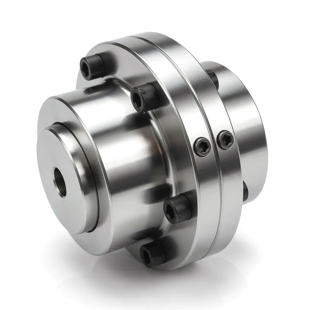
A gear coupling transmits torque through the meshed engagement of external gear teeth on the hub sleeve with internal teeth on the outer sleeve. The torque path runs: drive shaft → inner hub → external crowned gear teeth → internal sleeve teeth → outer sleeve → driven shaft. The crowned (barrel-shaped) profile on the external teeth is the functional key — it allows the mesh contact to roll slightly as angular offset occurs, rather than creating a hard edge-load concentration that would cause fretting and premature failure.
🔄 Misalignment Accommodation
Angular misalignment is absorbed by the rocking action of the crowned tooth profile within the sleeve. Axial displacement — caused by thermal growth — is accommodated by the axial sliding of sleeve teeth along the hub tooth flanks. Radial offset (parallel misalignment) is handled by a combination of angular deflection at each coupling half. Grease or oil lubrication in the sealed sleeve cavity maintains a thin film between mating surfaces, reducing friction heat generated by these compensating motions and protecting surface hardness layers from adhesive wear.
⚖ Dynamic Balance Principle
At 3,000 rpm, the centrifugal force generated by any residual unbalance mass in the coupling assembly is proportional to the mass, the eccentricity, and the square of rotational speed. ISO 1940-1 G2.5 balance grade limits the residual specific unbalance to 2.5 g·mm/kg — a very tight tolerance achieved through precision machining, balanced material stock selection, and individual balancing of assembled coupling units on high-accuracy balancing machines. Power station couplings from Ever Power are individually balance-stamped and shipped with calibrated balance reports as part of the QA package delivered to the commissioning engineer.
Core Materials in Power Station Coupling Manufacture
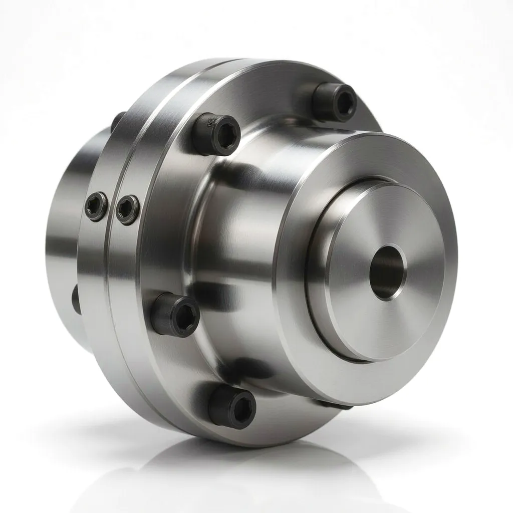
Material selection in power station couplings is driven by three competing requirements: high strength-to-weight ratio (to minimise rotational inertia), excellent fatigue resistance under cyclic thermal and mechanical loading, and good machinability to achieve the tight dimensional tolerances that precision balance demands. Alloy steels dominate the hub and sleeve manufacture, with specific grades chosen to optimise the combination of surface hardness (for tooth flank wear resistance) and core toughness (for shock-load resistance during synchronisation transients). Carburised and case-hardened low-alloy steel such as 20CrMnTi or 18CrNiMo7-6 delivers tooth flank hardness of 58–62 HRC while maintaining a ductile core that can absorb peak torque spikes without brittle fracture.
For sleeve bodies, through-hardened medium-carbon alloy steels such as 42CrMo4 (equivalent to SAE 4140 in North American specification) provide the combination of high yield strength (typically 850–1000 MPa) and reasonable toughness that the application demands. All raw material is sourced from certified mill stock with full traceability documentation, an increasingly important requirement for UK power station procurement under the Engineering Construction Industry Association (ECIA) supply chain frameworks. Sealing elements use fluoroelastomer (FKM) O-rings and lip seals rated to 150°C continuous service, compatible with both mineral-base grease and synthetic PAO lubricants commonly specified by turbine OEMs.
Hub Sleeve Gear Teeth
18CrNiMo7-6 carburised steel, case depth 1.2–1.8 mm, surface hardness 58–62 HRC
Outer Sleeve Body
42CrMo4 through-hardened, Rm ≥ 900 MPa, impact toughness KU2 ≥ 40 J at -20°C
シーリングシステム
FKM O-rings + PTFE-lined lip seals, service temp -40°C to +180°C, compatible with PAO and mineral-base greases
Fasteners
Grade 12.9 alloy steel bolts with locking inserts, all torque-certified and individually marked for traceability
Product Technical Advantages
卓越したトルク密度
Gear couplings achieve torque transmission densities of 50–150 N·m per kilogram of coupling mass — among the highest of any flexible coupling type. This is essential in power generation where rotating inertia must be minimised to keep torsional natural frequencies above operating speed and avoid resonance during speed ramp-up. A lighter coupling also reduces bearing radial loads at both the turbine exit bearing and the generator drive-end bearing, extending bearing service intervals.
Superior Fatigue Life — 100,000+ Hours
Power station couplings from Ever Power are designed and validated to exceed 100,000 cumulative operating hours — the equivalent of over 11 years of continuous service. This is achieved through combination of conservative design safety factors (minimum 2.5x on tooth bending fatigue), high-quality case-hardened gear steel, and precision-controlled grinding of tooth profiles to DIN 3962 quality grade 5 or better. Fatigue testing follows AGMA 9003 protocols, and every batch production run includes destructive test pieces from the same heat as production components.
High-Precision Dynamic Balance — G2.5
Every power station coupling assembly is individually balanced on our factory’s high-speed balancing rig to ISO 1940-1 Grade G2.5 or better. At 3,000 rpm with coupling masses in the range of 50–500 kg, this balance grade limits residual centrifugal force to levels well below the bearing load limits specified by turbine OEMs such as Siemens, GE, and Ansaldo. Balance correction is applied through removal of material from designated balance correction planes, and all balance data — residual unbalance, correction plane details, and final balance grade — is documented on the Quality Assurance certificate shipped with every unit to the power station site.
Angular and Axial Compensation
Standard power station gear couplings accommodate angular misalignment up to ±0.5° per gear mesh (±1.0° total across a double-engagement coupling) and axial displacement in the range of ±10 mm to ±50 mm depending on coupling size class. These compensation values are specifically calibrated to cover the worst-case thermal expansion scenarios modelled in turbine foundation design, ensuring that even during abnormal operating conditions — such as partial load trips or rapid cooling events — the coupling operates within its rated compensation envelope and does not transmit excess bending moment to adjacent bearings.
Product Technical and Performance Parameters
Broader Industrial Application Scenarios for Couplings
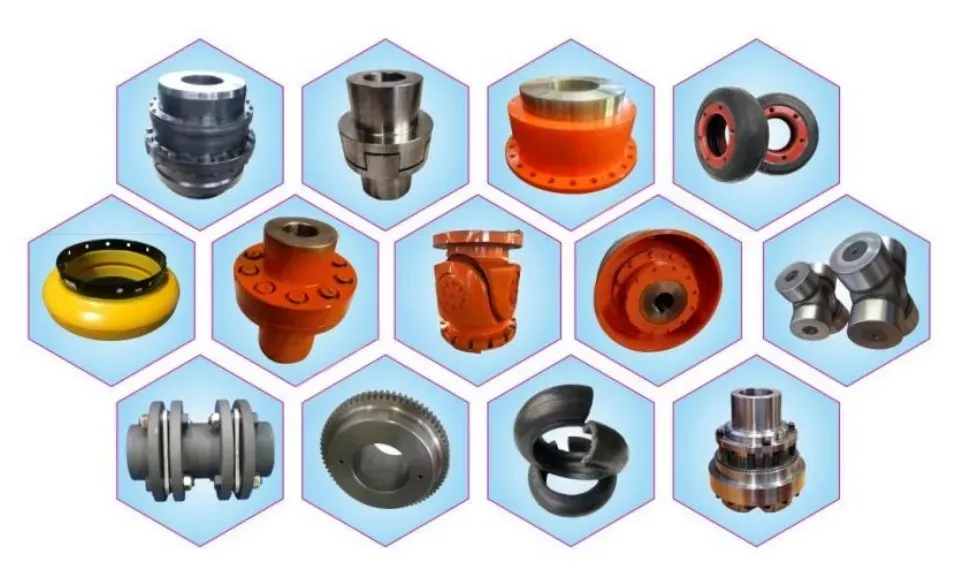
Beyond thermal power generation, couplings in the same torque and speed performance class serve a wide range of demanding UK industrial sectors. The engineering requirements vary — sometimes lubrication-free operation is essential, in other cases it is the ability to absorb shock loads from reversing drives — but the common thread is the need for precision-manufactured coupling components backed by full technical documentation. Ever Power supplies to the following sectors, typically through direct sale or via regional engineering distributors operating from Sheffield, Manchester, Bristol, and Leeds.



Featured Coupling Products from Ever Power
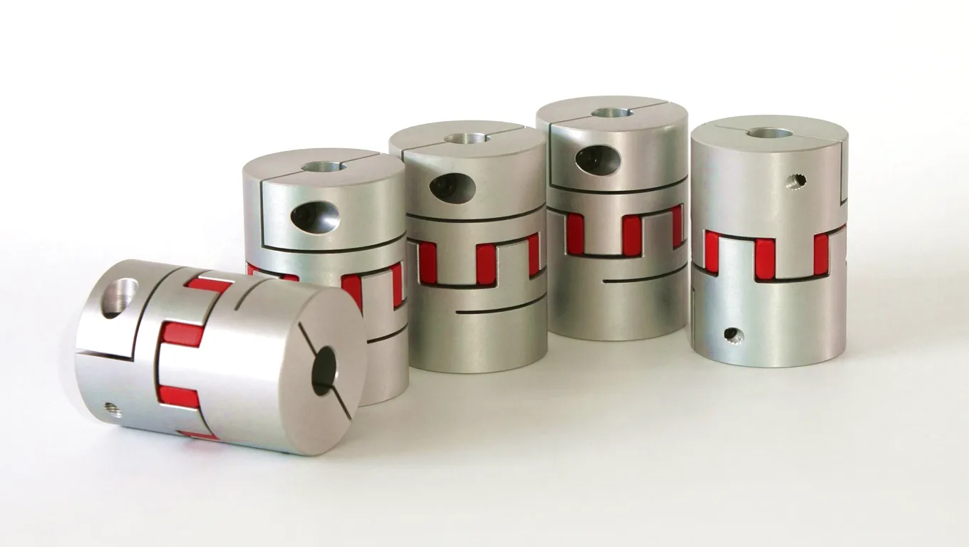
The Flexible Beam Coupling from Ever Power is a precision-machined single-piece helical-cut coupling designed for servo motor, encoder, and motion-control applications where zero backlash and high torsional stiffness are equally important. Machined from solid aluminium or stainless steel billet, its helical cut pattern provides angular and parallel misalignment compensation without the wear or lubricant degradation associated with jaw or gear couplings. Bore sizes range from 4 mm to 30 mm, making it the ideal solution for UK precision machine tool builders in Birmingham’s tooling cluster or Scotland’s semiconductor equipment sector requiring a maintenance-free, dynamically quiet coupling with predictable stiffness characteristics across its operating temperature range.
Ever Power’s Disc Coupling series delivers maintenance-free, lubrication-free flexible transmission for turbomachinery, compressor, and high-speed pump applications. Torque is transmitted through a pack of thin stainless-steel disc elements bolted alternately to the hub and the spacer — a configuration that provides high torsional stiffness combined with angular and axial flexibility without any sliding contact surfaces. This eliminates the lubrication requirement that gear couplings carry, reducing maintenance overhead for UK power station and offshore facility operators. Disc packs are field-replaceable without removal of the coupling hubs, significantly reducing planned maintenance downtime. Balance grades to G1.0 are standard for high-speed turbine applications operating above 5,000 rpm.
Customer Success Story: Drax Power Station, North Yorkshire
In 2023, a maintenance engineering team at a large biomass-converted power generation facility in North Yorkshire faced an increasingly difficult coupling management problem. The facility’s six generating units — each rated at approximately 660 MW — had accumulated over 90,000 operating hours on their original turbine-to-generator ギアカップリング assemblies. Vibration monitoring data was showing a clear upward trend in 1x running speed vibration at the generator drive-end bearing, suggesting that residual unbalance in the ageing coupling assemblies was increasing as component wear progressed. The maintenance window available for coupling replacement on each unit was just 72 hours — a constraint imposed by grid supply commitments under the facility’s capacity market agreement with National Grid.
The engineering team contacted Ever Power after a recommendation from a former colleague who had used our coupling products in a Sheffield steel plant application. Following a detailed technical review of the existing coupling configuration — including shaft end dimensions, spacer length, flange bolt circle, and the vibration spectrum data — Ever Power’s engineering team proposed a like-for-like replacement coupling in 18CrNiMo7-6 carburised steel, with the same external dimensions as the original units but with improved crowned tooth profile geometry (generated to DIN 3962 Grade 5 standard against the original Grade 7 specification) and an upgraded FKM seal specification compatible with the higher-viscosity synthetic lubricant the facility had adopted following a lubricant rationalisation programme. Every coupling was balanced to G2.5 and shipped with a full QA package including CMM inspection data and the balance report.
Installation on the first unit was completed by the facility’s on-site mechanical team in 58 hours against the 72-hour window — including laser alignment of the new coupling, pre-lubrication with the specified PAO grease, and a slow-roll check before returning the unit to service. Post-installation vibration measurements on the generator drive-end bearing showed a 78% reduction in 1x running speed amplitude compared to the readings recorded on the old coupling, confirming that the improvement in balance quality was the primary driver of the vibration trend the team had been tracking. The facility subsequently placed orders for replacement couplings on all remaining units, completing the refurbishment programme over four planned outages across an 18-month period.
“The improvement in vibration performance after fitting the Ever Power replacement couplings was immediately measurable — our drive-end bearing 1x amplitude dropped by well over 70% on the first unit we refurbished. The QA pack they provided, with individual balance reports and CMM data for every coupling, was exactly what our audit team needed for the maintenance record. Delivery was exactly on the promised date, which made our outage planning straightforward.”
— Senior Mechanical Engineer, Biomass Power Station, North Yorkshire
“We specified Ever Power disc couplings for a new pump skid package at our water treatment works outside Manchester. What stood out was the engineering support during the specification stage — their team modelled the torsional behaviour of our variable-speed drive system and confirmed that the standard stiffness specification was appropriate. That level of pre-sale technical input saved us significant engineering time and gave us confidence we’d selected the right product for the dynamic environment.”
— Mechanical Design Manager, Water Utility Infrastructure, Greater Manchester
“As a rolling mill OEM with customers across the UK and Northern Europe, we’ve trialled couplings from multiple suppliers for our main drive spindle packages. Ever Power’s gear couplings have consistently given us the lowest tooth wear rates and best retained balance quality at our 36-month inspection intervals. Their willingness to work with us on non-standard bore configurations and flange arrangements means we can integrate their products cleanly into our machine designs without compromise.”
— Head of Mechanical Engineering, Steel Mill Equipment OEM, Sheffield
よくある質問
Ready to Specify Your Coupling Solution?
Talk to Ever Power’s technical team about your torque rating, bore dimensions, and delivery requirements. We respond to all technical enquiries within one business day.