
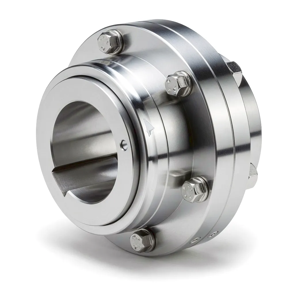
 Tunnel boring machines represent the most demanding end of modern underground engineering. Whether it is Crossrail’s eastern drives beneath London, HS2’s northern approach tunnels, or the water utility upgrades threading beneath Manchester and Birmingham, TBMs are working at the very edge of mechanical endurance. At the heart of these colossal machines lies the cutter head drive system — an assembly where extraordinary rotational torque, relentless vibration, and the ever-present risk of momentary overload must all be absorbed, transmitted, and managed without interruption. The coupling connecting each traction motor to its planetary gearbox, and each gearbox to the cutter-head main bearing ring, is a component that sees conditions no laboratory test fully replicates. This is precisely where the gear-type coupling has earned its place as the industry’s preferred torque-transmitting solution. Gear couplings combine the radial and axial flexibility needed to accommodate unavoidable shaft misalignment with the metal-to-metal contact geometry that alone can handle torques running from tens of kilonewton-metres right up to values exceeding 500 kN·m in the largest hard-rock TBMs currently cutting through the geology beneath the United Kingdom.
The Cutter Head Drive System: Where Gear Couplings Face Their Hardest Test
A modern large-diameter TBM — say, one cutting a 10-metre bore through London Clay or the Chalk Marl beneath the South Downs — typically deploys between six and eighteen electric drive motors arranged in a ring around the cutter head bulkhead. Each motor output shaft feeds into a dedicated planetary gearbox, which multiplies torque while reducing speed down to the 1–4 RPM range at which the cutter head rotates under full face pressure. The combined installed power can exceed 6,000 kW, and aggregate torque values measured at the main bearing ring often surpass 50,000 kN·m for soft-ground machines and exceed 100,000 kN·m for mixed-face and hard-rock variants. Within this architecture, gear-type couplings appear at two critical interfaces: between each drive motor and its associated planetary gearbox, and between each gearbox output flange and the main bearing drive ring. At the motor-to-gearbox interface, the coupling must accommodate angular and radial misalignment introduced by thermal expansion of the motor frame, manufacturing stack-up tolerances in the motor mounting plate, and vibratory displacement caused by the shield itself rocking against the ground reaction. At the gearbox-to-ring interface, the gear coupling must transmit peak torque surges that occur when a disc cutter strikes a hard inclusion or a face collapse momentarily jams the head — events that can multiply instantaneous load by a factor of 2.5 or more above rated torque. Gear couplings handle this through the contact kinematics of their crowned external-gear teeth engaging the straight internal gear teeth of the outer sleeve, a geometry that distributes load across multiple tooth pairs simultaneously and allows angular deflection of up to 1.5 degrees without stress concentration.
The crowned tooth profile — the defining characteristic that separates a true gear coupling from simpler jaw or pin-bush designs — is machined to a precise barrel or spherical convex form. Under misaligned running conditions, the crowned teeth rock smoothly within the internal sleeve bore, maintaining full load-sharing across the tooth width even when the shaft centrelines diverge by the full permitted angle. This behaviour makes the gear-type coupling fundamentally different from a rigid flange coupling, which would transmit the misalignment as a bending moment directly into the shaft and bearing housings, causing fatigue failures in drive trains designed to run continuously for hundreds of thousands of operational hours beneath a British city.
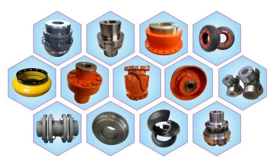
Working Principle of Gear-Type Couplings in High-Torque Drive Trains
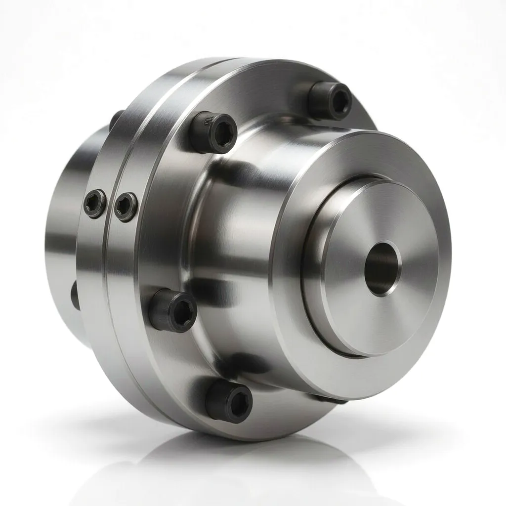
The operating principle of a gear-type coupling rests on the controlled relative motion between an external gear hub and an internal gear sleeve. Each hub is machined with a set of involute spur or helical teeth on its outer diameter; the sleeve is a cylindrical housing whose bore carries matching internal teeth. Unlike a fixed gearset where all tooth contact forces are purely radial, the coupling’s crowned external teeth deliberately introduce a degree of convexity along the tooth face. When both shafts are perfectly collinear, load is shared equally across the full tooth width. When misalignment exists — angular, radial, or axial — the crowned geometry allows the engagement zone to migrate across the tooth face without edge loading. This migration distributes the contact stress over a larger area than would otherwise be possible, fundamentally extending fatigue life.
Torque is transmitted purely through tooth-flank contact — no rubber elements, no elastomers, no intermediate compliance medium. This makes the gear coupling essentially rigid in torsion while remaining flexible in bending, a combination that is extremely difficult to achieve with other coupling types. In TBM applications, this torsional rigidity is critical: it preserves the accuracy of speed-differential sensing between adjacent drive motors, which the PLC-based main drive controller relies upon to balance load sharing across all drives. If one coupling were to introduce torsional compliance, the controller’s load-sharing algorithm would interpret the compliance as a speed difference and attempt to compensate, potentially overloading the drive furthest from the speed sensor. Gear couplings eliminate this ambiguity entirely.
Lubrication is the key maintenance parameter. The tooth contact zone generates heat through friction, and the lubricant — typically a semi-fluid grease with an NLGI consistency of 00 to 0, or a mineral/synthetic gear oil — must remain in the mesh under the centrifugal action of rotation. At TBM drive-speed ranges (typically 60–1,500 RPM at the motor-shaft coupling depending on gearbox ratio), centrifugal lubricant expulsion is not severe, making grease-packed configurations practical. Vertical orientation — common in shaft-sinking machines used in Scottish mining heritage sites and Northern Ireland infrastructure projects — requires sealed coupling designs to prevent drainage. Properly maintained, a gear coupling in a TBM drive train can achieve service intervals exceeding 5,000 operational hours before disassembly for inspection.
Core Materials: What Goes Into a High-Performance Gear Coupling
Material selection for gear-type couplings used in TBM drive systems is governed by three competing demands: the need for high surface hardness at the tooth flanks to resist pitting and wear, adequate core toughness to survive shock loading without brittle fracture, and sufficient machinability to allow the tight tolerances (IT6 or better) required for proper mesh geometry. Engineering teams specifying couplings for UK tunnel contracts — where machines may run around the clock for eighteen months or more without easy access for unplanned maintenance — demand materials with well-documented fatigue properties and full material traceability certificates.
Application Scenario: Tunnel Boring Machines and Underground Infrastructure
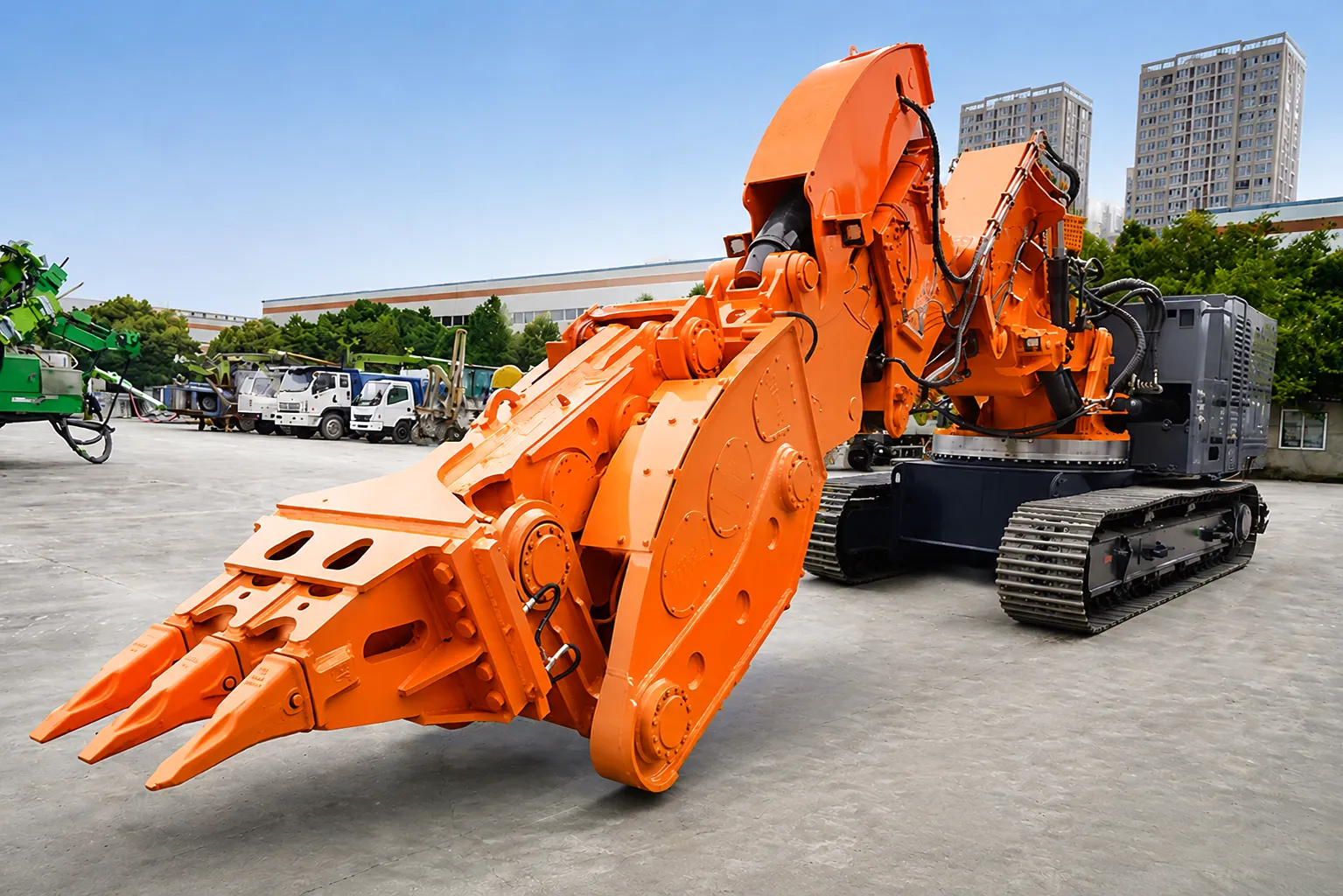
Tunnel boring machines are the backbone of modern underground construction, and their appetite for robust mechanical components is unmatched in the broader industrial landscape. The cutter head of a TBM is driven through a torque transmission chain that begins at each motor shaft and ends at the main bearing ring — the structure that ultimately pushes hundreds of hardened disc cutters against the tunnel face with forces measured in thousands of kilonewtons. In the United Kingdom, the scale and pace of underground infrastructure investment has placed TBM-related mechanical component supply firmly in the spotlight. Projects beneath London’s streets, the rail tunnels threading through the Pennines, and the water main refurbishment programmes in Sheffield and Leeds all rely on drive components capable of running continuously through the punishing conditions of subterranean construction.
Between each electric motor and its planetary gearbox, a gear-type coupling must simultaneously absorb rotor imbalance vibration from the motor, accommodate the thermal expansion differential between the motor frame and the gearbox housing, and transmit rated torque continuously while surviving overload pulses that arrive without warning and with amplitudes of 200–300% above the steady-state value. The coupling’s ability to flex angularly by 0.5–1.5 degrees during these events — rather than transmitting the bending moment rigidly into the motor bearing — directly determines motor bearing life. Engineers at major UK tunnel contractors working on projects from the Thames Tideway to the M25 Junction 10 improvement tunnels have confirmed that gear coupling specification is a critical design decision, not a standard-component choice, precisely because the consequences of a coupling failure underground are so severe: a failed coupling means a TBM stoppage, which in a pressurised-face machine means face stabilisation procedures, water ingress management, and potentially tens of thousands of pounds of delay costs per day.
Between each gearbox output and the drive ring, the coupling functions under lower rotational speed but far higher torque magnitudes. In a 9-metre-diameter EPB machine cutting London Clay beneath Crossrail’s route, this interface sees torque values that would destroy any jaw coupling or elastomeric design within hours. Only the metal-to-metal contact geometry and heat-treated tooth flanks of a properly specified gear coupling can sustain the Hertzian contact pressures involved. The coupling at this interface must also tolerate a degree of wobble in the drive ring as the cutter head reacts to ground inhomogeneity — a radial misalignment whose magnitude changes continuously during operation. This dynamic misalignment environment is the gear coupling’s natural habitat.
Underground Mining and Shaft Sinking: Adjacent UK Applications
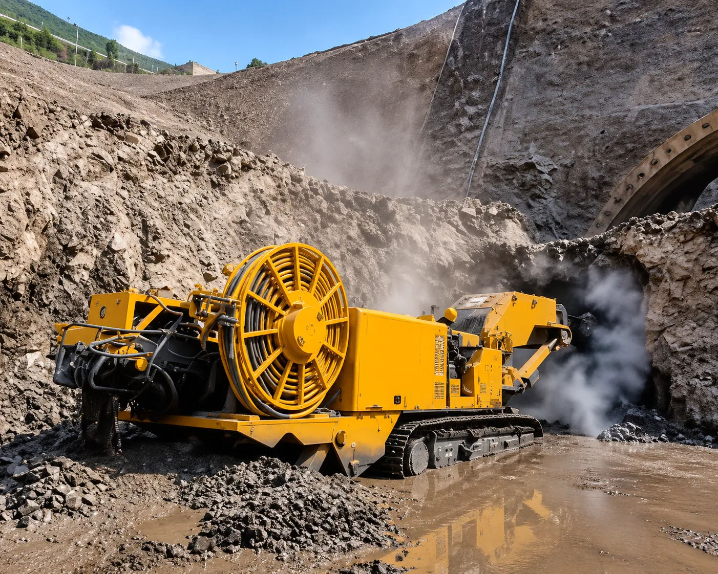
Beyond tunnel boring, gear-type couplings find extensive application across the broader spectrum of underground construction and mining plant operating in the UK. Shaft sinking rigs — used to establish ventilation shafts, emergency egress points, and cable routes for major tunnelling projects — employ multi-drum hoisting winches driven by high-power electric motors through planetary gearboxes. The coupling between motor and gearbox must withstand the shock load generated at every clutch engagement and every emergency stop: conditions that favour the same crowned-tooth, metal-to-metal contact geometry that makes gear couplings indispensable in TBM drives. In legacy British mining regions including Nottinghamshire, South Wales, and parts of North Yorkshire where deep borehole drilling for geothermal energy extraction is now replacing coal extraction, gear couplings connect the top-drive motors to the kelly shaft of drilling rigs, a connection point that sees both full rated torque and significant angular displacement as the drill string bends under the lateral forces of directional drilling.
The surface plant serving these underground operations — crusher drives, conveyor head drives, slurry pump drives, and fan station assemblies — also uses gear couplings extensively. Birmingham-based heavy equipment maintenance contractors frequently specify gear-type couplings for crusher main shaft applications because the coupling’s ability to accommodate the shaft movements caused by crushing-chamber wear and the consequent shift in bearing housing positions allows service intervals to be extended without shaft realignment. In Sheffield, steel-industry legacy sites now repurposed as battery gigafactory construction zones have highlighted a related need: gear couplings connecting the large compressor and chiller drives that support lithium-cell formation environments, where torque demand is steady but shaft alignment changes seasonally with thermal expansion of the plant structure.
Product Advantages: Why Gear Couplings Outperform Alternatives in TBM Service
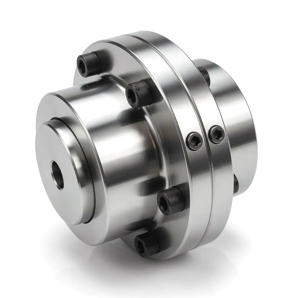 When procurement teams at major UK tunnel contractors evaluate coupling options, the technical comparison consistently resolves in favour of gear couplings for the most demanding drive positions. Elastomeric couplings — highly effective in lower-power applications and motor-pump sets — cannot transmit the torque densities required in TBM drives without becoming prohibitively large and heavy, and their torsional compliance introduces the load-sharing control interference described above. Disc-pack couplings offer excellent torsional rigidity and reasonable misalignment tolerance, but their bending stiffness makes them sensitive to radial misalignment and their fatigue life in shock-loading environments is shorter than carburised gear couplings. Chain couplings are inexpensive but wholly unsuitable for TBM applications due to their low torsional stiffness, sensitivity to dirt ingress, and inability to handle the combination of high torque and continuous misalignment.
Product Technical & Performance Parameters
The table below covers the principal performance envelope of gear-type couplings as applied across the TBM drive and underground equipment sector. Values represent standard product ranges; Ever Power’s engineering team can extend parameters through custom design for specific project requirements.
| Parametru | Gamă standard | Heavy-Duty TBM Grade | Unit / Note |
|---|---|---|---|
| Rated Torque (Tn) | 500 – 100,000 | 50,000 – 500,000 | N·m |
| Peak Torque (overload) | 2.0 x Tn | 2.5 – 3.0 x Tn | Transient, max 3 sec |
| Nealiniere unghiulară | Up to 1.0° | Până la 1,5° | Per coupling element |
| Radial Offset (double-end) | 0.3 – 0.8 mm | Up to 1.2 mm | At rated speed |
| Deplasare axială | +/- 3 – 8 mm | +/- 5 – 15 mm | Per coupling |
| Max Speed (unbalanced) | 500 – 3,000 | 200 – 1,500 | RPM |
| Materialul butucului | 40Cr / 42CrMo4 | 42CrMo4, carburised | Heat-treated per GB/T |
| Duritatea suprafeței dintelui | 52 – 58 HRC | 58 – 62 HRC | Case depth 0.8–1.5 mm |
| Temperatura de funcționare | -20 to +80 °C | -30 to +120 °C | With appropriate grease |
| Interval de lubrifiere | 2,000 – 4,000 hrs | 4,000 – 8,000 hrs | Sealed design: up to TBO |
| Protection Rating | IP54 | IP65 – IP67 | Sealed flange variant |
| Balancing Grade | G6.3 (ISO 1940-1) | G2.5 or better | Dynamic balance |
Featured Coupling Products from Ever Power
Two products from our catalogue that serve adjacent high-torque and flexible shaft coupling applications in UK industrial projects:
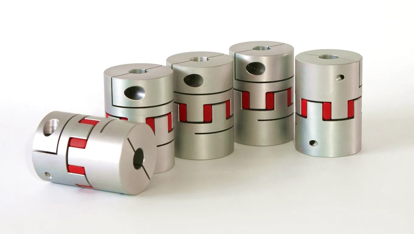
The JSA Series Snake Spring Coupling uses a corrugated steel spring element wound between two slotted flanges to deliver outstanding torsional flexibility with no rubber components. It excels in applications with moderate misalignment, vibration damping requirements, and frequent torque reversals — making it a valued alternative where elastomeric fatigue is a concern.
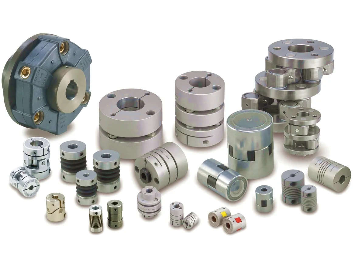
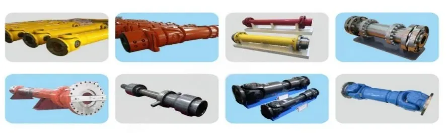
The SWC Series Universal Coupling (Cardan-type) transmits torque between shafts at large intersection angles — up to 15 degrees per joint — without loss of rotational uniformity. Widely deployed in rolling mill drives, steel plant equipment, and large fan shaft connections across UK heavy industry. Available with bearing-type crosses for high-cycle reliability.
Ever Power: Precision Manufacture & Custom Coupling Solutions
Ever Power has built its reputation over more than two decades as a specialist manufacturer of high-performance gear-type couplings, universal couplings, and ancillary power transmission components serving some of the world’s most demanding industrial applications. The manufacturing facility — spanning over 18,000 square metres of covered production floor — operates CNC gear hobbing, gear grinding, and precision boring centres working to tolerances of 0.005 mm on critical coupling dimensions. Heat treatment is conducted in-house in a controlled atmosphere carburising furnace suite, and every batch of alloy steel arrives with full mill certificates traceable to the melt. This level of supply-chain discipline is not incidental: it is the direct response to the needs of UK project managers who require component traceability documentation as a condition of contract on infrastructure projects governed by the Construction (Design and Management) Regulations and covered by PAS 2080 carbon-value engineering frameworks.
The customisation capability at Ever Power covers every dimension of coupling design. Bore sizes, keyway geometry, interference-fit tolerances for hydraulic mounting, flange bolt-circle diameters, tooth module and pressure angle, case-hardening depth, sealing arrangement, and surface coating can all be modified to match the exact requirements of a specific drive position on a specific machine. For UK clients working on TBM projects where the coupling must interface with a German-made gearbox on one side and a British-sourced motor mounting plate on the other, this boundary-crossing capability is not a luxury but a necessity. The engineering team at Ever Power includes mechanical engineers with direct experience of drive train design for underground equipment, meaning technical dialogue with procurement engineers and project managers can occur at the level of engineering detail rather than catalogue specification. Lead times for custom-designed gear couplings are typically 8–14 weeks from drawing approval to despatch, with express manufacture achievable in 4–6 weeks for emergency replacement of failed units on live TBM projects.
Povestea de succes a clientului
A major civils contractor engaged in the extension of underground metro infrastructure beneath central Birmingham faced a critical schedule problem midway through a twin-bore tunnelling drive. One of the primary EPB machines had developed abnormal vibration signatures on two of its twelve motor-to-gearbox coupling positions. Inspection during a planned maintenance window revealed that the original coupling supplier’s components — selected on price rather than specification — had experienced tooth-flank pitting fatigue in both units after only 4,200 operational hours, less than half the expected service interval. The contractor’s engineering team contacted Ever Power seeking urgent replacements that could be manufactured to match the existing gearbox input interface while improving tooth geometry for greater fatigue resistance in Birmingham’s dense clay-with-gravel stratigraphy, where face torque variability is higher than in pure clay drives.
Ever Power’s engineering team reviewed the failed couplings’ dimensional data and operating logs, identifying that the original design’s tooth crown radius had been inadequate for the misalignment levels present at this particular motor-mounting configuration. A revised coupling was designed with an increased crown radius of 2,800 mm, bringing the tooth contact pattern to a more central position under the actual misalignment conditions of the drive. Material was specified as 42CrMo4 with carburising to 1.2 mm effective case depth, heat-treated to 60 HRC at the tooth surface and 30 HRC at core — a significant uplift from the original components. The replacement couplings were manufactured, ground, balanced, and delivered to the Birmingham site within 21 working days of drawing approval, allowing the TBM drive to resume within a single planned maintenance shift rather than requiring an extended shutdown.
By the time the drive was complete — a total bore of 2.3 km through varied ground conditions including sections through historic brick-arch infrastructure — the replacement Ever Power couplings had accumulated 9,600 operational hours without any maintenance intervention beyond the scheduled lubrication top-ups. The contractor’s project manager noted that the absence of coupling-related downtime over the second half of the drive contributed directly to the project coming in six weeks ahead of its revised programme target.
“The gear couplings from Ever Power performed beyond expectations. After 9,600 hours underground through some genuinely difficult Birmingham ground, there was no measurable tooth wear when we stripped them down at drive completion. The crown geometry they redesigned for us is clearly doing exactly what it should.”
“What made Ever Power different was the engineering conversation we were able to have before the order was placed. They understood our misalignment conditions and didn’t just supply a catalogue part — they redesigned the crown radius and came back with clear fatigue life projections backed by calculation. That kind of technical accountability is rare.”
“The 21-day turnaround from drawing approval to delivery on site — including custom machining, heat treatment, and dynamic balancing — was genuinely impressive. We had planned for a six-week delay and had to revise our recovery programme upward when the parts arrived ahead of time. The coupling performance since installation has been faultless.”
Întrebări frecvente
Common questions from UK procurement engineers, plant managers, and tunnel project teams
FAQPage + Speakable JSON-LD structured data for this article should be added in the WordPress post’s HTML source using a script tag in the document head or via a structured data plugin (e.g. Rank Math, Yoast). The schema includes all FAQ questions above, marked up to Google’s FAQPage specification and Speakable guidelines for voice-search eligibility. Paste your JSON-LD block as provided separately into the page head — do not place it inside the post body HTML as WordPress may strip script tags from post content.