
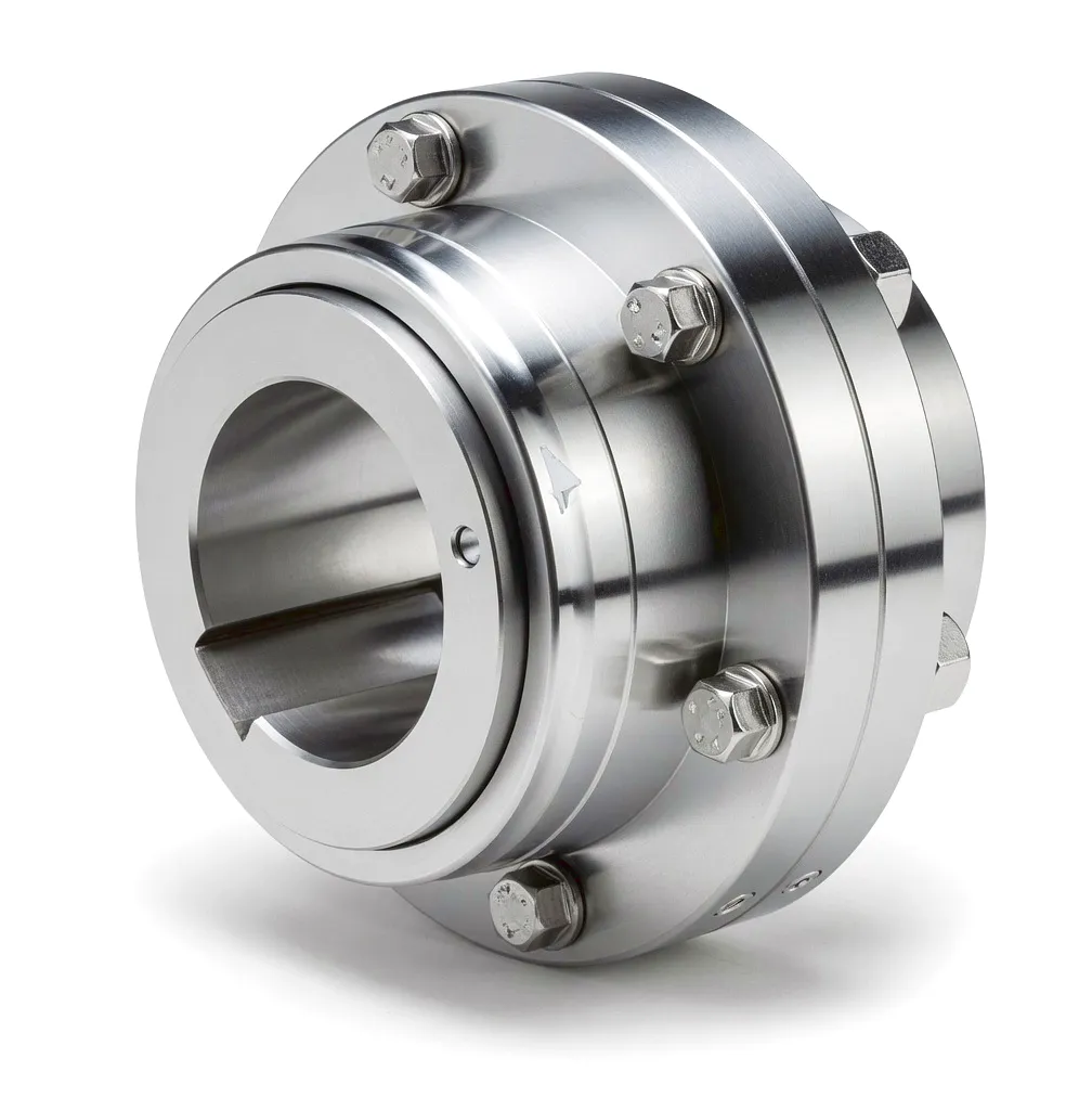
The transmission coupling occupies a position of extraordinary consequence inside any thermal power plant. Sitting between the steam turbine shaft and the generator rotor, this single mechanical component must silently absorb the physical contradictions of industrial power generation: enormous torque transmitted at high rotational speed, continuous thermal cycling that shifts shaft centrelines by millimetres, torsional impulses from grid load fluctuations, and the absolute commercial imperative of uninterrupted service across years-long maintenance intervals. In the United Kingdom, where ageing coal plant retirements have accelerated the commissioning of gas-fired combined-cycle units and biomass co-generation facilities at locations from Drax in North Yorkshire to the Severn Estuary, the specification of the right coupling is no longer a detail — it is a station-level engineering decision.
The output capacity of large thermal power sets in service across the UK ranges from approximately 50 MW at industrial co-generation installations to well over 600 MW at combined-cycle gas turbine (CCGT) stations. At these power levels, the coupling must transmit peak torque values measured in hundreds of kilonewton-metres while rotating at synchronous speeds of 3,000 rpm (for 50 Hz grid-tied generators) or higher for intermediate-pressure shaft stages. The mechanical demands are severe by any standard, and they arrive simultaneously rather than in sequence. Only a coupling engineered specifically for this duty — with precisely calculated geometry, premium-grade alloy steel, and dynamic balance verified to G2.5 grade or better — can satisfy all of these requirements across a service life that industrial operators in Birmingham, Sheffield, and Teesside measure in decades rather than years.
How Couplings Work in Steam Turbine Drive Trains
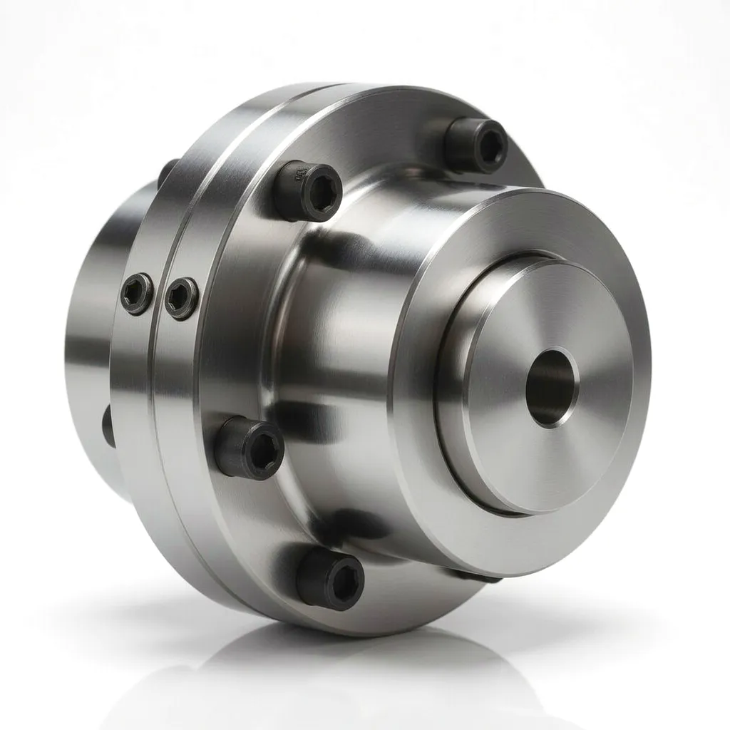 At its core, a coupling transmits rotational torque from a driving shaft — in this case the turbine output — to a driven shaft, the generator rotor, while accommodating the inevitable misalignment between the two. In a thermal power environment, this misalignment is not a manufacturing defect: it is a thermodynamic inevitability. As the turbine reaches operating temperature, thermal expansion moves the shaft axis in both the radial and axial planes. A rigid connection under these conditions would introduce enormous bending stresses into both the turbine bearing journal and the generator shaft, accelerating fatigue damage at a rate entirely incompatible with the maintenance schedules that UK power station operators plan around. The coupling’s role is to decouple (in the mechanical sense) the two rotors from each other’s deformation fields while maintaining precise torque transmission continuity.
Gear-type couplings achieve this through an interface of precision-ground external teeth on two hubs meshing against internal teeth on a sleeve. The crowned tooth profile — slightly barrel-shaped in the axial cross-section — allows angular misalignment of up to approximately 1.5° per gear mesh while maintaining full flank contact across the load-bearing tooth face. Axial displacement is accommodated by a sliding fit between hub and sleeve, lubricated with high-temperature grease or oil mist under sealed cover plates. This seemingly simple mechanism delivers an extraordinary combination of torque density and misalignment tolerance that no flexible polymer element can match at turbine-scale power ratings.
The torsional dynamics of the coupling are equally important. Grid-connected generators experience sudden changes in electromagnetic torque whenever load switching, short-circuit events, or frequency disturbances occur on the national transmission system. These torque spikes are transmitted back through the coupling into the turbine shaft system. A coupling with appropriate torsional stiffness acts as a mechanical filter: stiff enough to maintain synchronism and avoid resonance at running speed, but not so rigid that transient overloads are transmitted without attenuation. For UK power plants connected to National Grid’s transmission network, this torsional behaviour must be validated through rotor dynamic analysis in accordance with the connection standards applied by the relevant network operator.
Dynamic balance is the third fundamental principle. At 3,000 rpm, even a small residual mass imbalance in the coupling assembly generates a centrifugal force — proportional to the square of speed — that excites the rotor system at running frequency. UK turbine manufacturers and power station engineers therefore specify dynamic balance to ISO 21940-11 Grade G2.5 as a minimum, with critical machines requiring G1.0. This demands balance correction at two planes, precision-machined balance pads on the sleeve, and verification on a calibrated high-speed balance machine before the coupling leaves the manufacturing facility. Ever Power’s production line includes dedicated balance rigs capable of verifying assemblies to G1.0 across the full range of coupling sizes used in UK power generation.
Core Materials in Power Generation Coupling Manufacture
⚙ Alloy Steel Hubs — 42CrMo4 / 34CrNiMo6
The hub is the highest-stress element in any gear coupling, combining torsional shear at the bore with bending stress at the root of the external gear teeth. Chromium-molybdenum steels such as 42CrMo4 (equivalent to BS EN 10083-3 grade) are the standard choice: after forging and heat treatment to the QT (quench-and-temper) condition, tensile strengths of 900–1,100 MPa are routinely achieved alongside excellent impact toughness at temperatures down to −20 °C. For the largest high-integrity coupling hubs used in 500 MW-class units, 34CrNiMo6 forgings provide an additional margin of strength and notch toughness that covers the impulsive loading scenarios described above. Forging rather than casting is specified for these hubs without exception: the grain flow alignment produced by forging significantly improves the fatigue strength of the tooth root fillet under cyclic loading.
⚙ Sleeve Fabrication — Case-Hardened Steel or Ductile Iron
The coupling sleeve carries the internal gear teeth and spans the gap between the two hubs. For smaller power ratings, high-strength ductile iron (GGG-70 or equivalent) offers excellent machinability and adequate strength while reducing rotating mass. For transmission couplings in large turbine drives, steel sleeves in 20MnCr5 or 16MnCr5, carburised and case-hardened to 58–62 HRC at the tooth flanks, are mandatory: the case provides the wear resistance needed for the sliding contact that occurs during thermal expansion cycles, while the tough core beneath resists brittle fracture under shock loads. Surface carburising depths of 0.8–1.5 mm are typical for power generation sleeves, verified by metallographic section inspection at Ever Power’s quality laboratory before dispatch.
⚙ Sealing and Lubrication Components
Long-term reliability in a continuously operating turbine depends as much on effective lubrication retention as on steel quality. Cover plates are typically manufactured in aluminium alloy or carbon steel with elastomeric O-ring seals rated for the operating temperature range — typically −20 °C to +120 °C for gear coupling grease in power station environments. Fluorosilicone or HNBR seal materials are specified where the environment includes steam leakage or condensate exposure, which is common in the turbine hall environments found at older UK generating stations where steam sealing standards may not fully contain vapour ingress to the coupling bay. High-temperature lithium-complex or polyurea greases with operating ranges to 200 °C are selected for power generation coupling lubrication, with re-greasing intervals matched to the scheduled outage programme.
Core Technical Advantages of Gear-Type Couplings for Power Generation
◈ Exceptional Torque Density
The gear mesh interface distributes load across multiple tooth contacts simultaneously, giving gear couplings a torque-to-diameter ratio far superior to jaw, disc, or elastomeric designs. For a given transmission torque requirement, the gear coupling can be smaller and lighter — reducing overhung moment on turbine and generator bearing journals — while retaining an adequate service factor for peak and transient loads. In UK CCGT plant where shaft arrangements are often constrained by existing civil structures, this compactness is a genuine engineering advantage rather than a theoretical one.
◈ Multi-Plane Misalignment Compensation
Thermal expansion in a large steam turbine does not move the shaft along a single predictable vector. The complex thermal gradients across the turbine casing and bearing pedestals produce combined angular and parallel misalignment in three dimensions. The double-flex gear coupling — two gear mesh planes separated by a floating spacer sleeve — accommodates this three-dimensional displacement field without imposing bending moments on the shafts. Angular misalignment up to 1° per mesh and axial displacement up to 15 mm are typical rated capacities for power generation classes of gear coupling, values that comfortably span the thermal excursion seen at rated power in a gas turbine drive train.
◈ Long Service Life — Over 100,000 Operating Hours
Power station operators, particularly those managing baseload assets under long-term capacity market agreements with NESO (National Energy System Operator), cannot afford unplanned outages driven by coupling failure. The design fatigue life of a properly specified gear coupling — with tooth geometry, material, and lubrication matched to the actual load spectrum — routinely exceeds 100,000 cumulative operating hours. This translates to over 11 years of continuous operation, well aligned with the maintenance intervals of modern CCGT units. Planned inspection and re-greasing during scheduled outages extend this life further, and Ever Power provides detailed inspection criteria and wear limit tables with every power generation coupling supplied to the UK market.
◈ High-Precision Dynamic Balance — G2.5 / G1.0
At synchronous speed on the GB grid (3,000 rpm for a two-pole generator), the centrifugal force from even a small residual imbalance is amplified by the square of the rotational speed. A 10-gram mass offset at 200 mm radius generates over 200 N of rotating force at 3,000 rpm — enough to measurably increase bearing load and excite the rotor system. Ever Power’s precision machining and dedicated balance verification processes achieve G2.5 as standard and G1.0 for critical applications, suppressing vibration excitation at source and extending the service life of turbine and generator bearings simultaneously. This is particularly valued by UK power station engineers who manage plant condition using continuous vibration monitoring under the requirements of their environmental and operational permits.
◈ Speed Rating to 3,000 rpm and Beyond
Two-pole generators on the 50 Hz UK grid run at exactly 3,000 rpm synchronous speed, while intermediate-pressure turbine shaft stages in multi-cylinder arrangements may rotate considerably faster. Gear couplings with precision-ground tooth profiles, verified dynamic balance, and properly sealed lubrication systems are inherently capable of operating at these speeds without self-excitation or fatigue accumulation that would compromise the rated life. Ever Power validates each coupling design for its maximum permissible speed using analytical models that account for centrifugal hoop stress in the sleeve, critical speed margins of the floating spacer (where applicable), and the permissible angular velocity at which the lubrication film in the gear mesh can be reliably maintained.
Product Technical & Performance Parameters
The table below covers the principal rated parameters for Ever Power gear-type couplings in the power generation size range. Values represent nominal ratings; specific application projects receive a custom analysis with detailed performance data.
| Параметр | Range / Value | Примечания |
|---|---|---|
| Номинальный крутящий момент | 500 N·m – 2,500 kN·m | Power generation range; custom capacity on request |
| Peak / Transient Torque | Up to 2.0 × rated torque | Short-circuit / grid fault scenario |
| Максимальная скорость | Up to 6,000 rpm (size-dependent) | 3,000 rpm standard for 50 Hz 2-pole generators |
| Угловое смещение | До 1,5° на каждое зацепление шестерен | Double-flex: up to 3° total system accommodation |
| Осевое смещение | ± 5 mm to ± 25 mm | Thermal expansion accommodation |
| Материал ступицы | 42CrMo4 / 34CrNiMo6 alloy steel | Forged and heat-treated; tensile 900–1,100 MPa |
| Материал рукава | 20MnCr5 / 16MnCr5 (case-hardened) | Surface 58–62 HRC; case depth 0.8–1.5 mm |
| Balance Grade | G2.5 standard / G1.0 premium | Per ISO 21940-11; two-plane correction |
| Рабочая температура | −20 °C to +120 °C (grease); to +200 °C (polyurea) | Seal material selected for application environment |
| Design Service Life | > 100,000 operating hours | Subject to correct lubrication maintenance |
| Tooth Profile | Involute / crowned (barrel-profiled flanks) | Ground finish; accuracy class DIN 3960 Grade 6 or better |
| Диапазон диаметров отверстий | 30 mm – 600 mm | Custom keyway, interference, and hydraulic-fit options |
Industrial Application Scenarios for Power Generation Couplings




Featured Ever Power Coupling Products
Two couplings from the Ever Power range that are particularly suited to power generation and high-torque industrial drives:
⚙ Flexible Beam Coupling
The Гибкое соединение балок is a compact, zero-backlash coupling ideal for precision drive trains including servo-motor connections, measurement drive systems within power plant control rooms, and smaller auxiliary equipment. Its single-body helical-cut beam construction allows angular and axial misalignment to be accommodated with very low restoring forces, making it an excellent choice where bearing side-load must be strictly controlled. The aluminium or stainless steel body is lightweight yet mechanically rigid in the torsional direction, ensuring accurate position transmission in electrically driven auxiliary systems. Available in bore diameters from 3 mm to 40 mm, suitable for all standard motor shaft sizes used in UK plant auxiliary equipment.
⚙ Disc Coupling
The Дисковая муфта uses a stack of precision-formed metallic disc packs to transmit torque while accommodating angular and axial misalignment through elastic deformation of the disc elements. This design is entirely maintenance-free — no lubrication required — and handles torsional loads with very high precision and minimal backlash, making it the preferred choice for demanding drive train applications including high-speed pump drives, compressor applications, and generator couplings at medium power ratings. The stainless steel disc pack withstands operating temperatures up to 200 °C and offers excellent resistance to fatigue under cyclic loading, giving the disc coupling a service life that rivals gear couplings in well-maintained drive trains. Available with spacer configurations for drop-out access without disturbing the coupled machines.
Ever Power — Precision Manufacturing and Custom Coupling Solutions
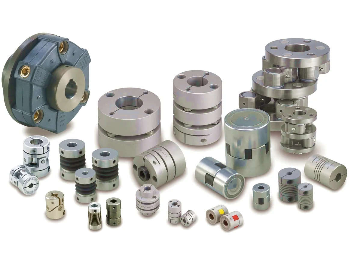 Ever Power has built its reputation as a precision manufacturer of industrial couplings through a combination of investment in manufacturing technology, rigorous quality systems, and a genuine engineering approach to every application. The company’s manufacturing facility operates multi-axis CNC gear grinding centres capable of producing crowned tooth profiles to DIN 3960 Grade 6 accuracy as a production standard, with Grade 4 achievable for critical applications where the highest level of tooth profile accuracy is required to suppress vibration generation at the mesh. Every coupling intended for power generation duty passes through our dedicated quality control sequence: material certificate verification, dimensional inspection with CMM traceability, hardness profile measurement on case-hardened components, and balance verification on calibrated balance equipment with certification to the ordered grade.
The supply chain that supports Ever Power’s power generation coupling range is itself built on precision: raw material forgings are sourced from certified suppliers with full traceability to heat certificate and delivery condition, allowing Ever Power to support the material documentation requirements of UK power station quality assurance programmes. Where customers require compliance with UK or European technical standards — BS EN, ISO, or specific OEM quality plans — Ever Power’s quality team reviews documentation requirements at order placement and ensures that the inspection and testing programme is planned to generate all required records before dispatch. Expedited logistics to UK power station sites across Great Britain is coordinated through our established freight partners, ensuring that scheduled outage timescales are met reliably.
Customisation Capabilities
Every power generation coupling project differs. Bore diameters and keyway configurations are application-specific; shaft end geometry may involve hydraulic interference fits, spline connections, or flanged-hub arrangements depending on the OEM turbine or generator design. Ever Power’s engineering team reviews all shaft end data provided by the customer and designs the coupling hub-to-shaft interface to achieve the required interference fit, keyway stress, or spline capacity with an appropriate safety factor. Custom heat treatment specifications, additional non-destructive testing (UT, MT), special surface coatings, and modified lubrication access provisions for in-situ re-greasing without coupling removal are all regularly accommodated within the standard manufacturing workflow.
Prototype and short-lead deliveries for urgent outage support — including the rush supply of replacement hubs for damaged couplings at UK power stations — are handled through a prioritised manufacturing slot system. Customers from across the UK, from Scottish Power facilities in Scotland to EDF Energy stations in the South of England, have relied on Ever Power’s ability to deliver replacement and upgrade coupling assemblies within compressed outage windows. Get in touch with our technical sales team to discuss your specific requirement.
Customer Success Story: Barnsley CHP Plant, South Yorkshire
Case Study · South Yorkshire · Industrial CHP · Ever Power Gear Coupling
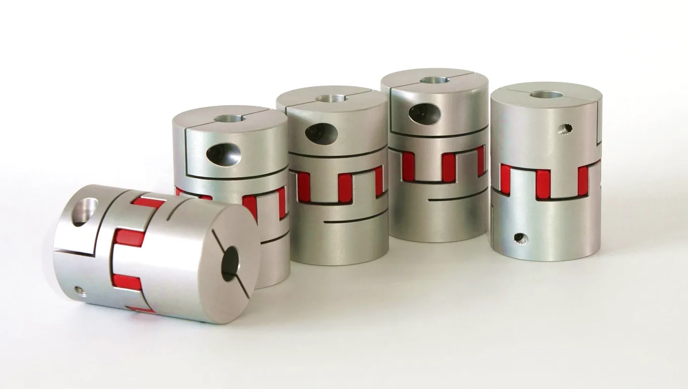 A major industrial chemicals manufacturer operating a site-scale combined heat and power plant at their Barnsley, South Yorkshire facility was experiencing repeated coupling failures on the gas reciprocating engine drive to the grid-connected generator. The original equipment coupling — a standard jaw-type elastomeric design — was failing approximately every eight to fourteen months, driven by fatigue of the elastomeric spider element under the torsional irregularity generated by the six-cylinder gas engine. Each failure triggered a planned outage of three to five days to replace the coupling, with associated production losses and the cost of reactive maintenance that the site energy manager estimated at over £180,000 per failure event when lost CHP income and overtime labour were accounted for.
The site engaged Ever Power’s technical team to review the application. Our engineering team conducted a torsional analysis of the complete drive train — engine, coupling, and generator rotor — using the measured torque irregularity data from the engine manufacturer and the torsional stiffness values of the existing and proposed coupling designs. The analysis revealed that the original coupling’s low torsional stiffness was placing a torsional natural frequency of the system close to the fourth harmonic of engine firing frequency at rated speed, resulting in resonant amplification of torque oscillations that exceeded the fatigue limit of the elastomeric element within the observed failure timeframe.
Ever Power specified a custom gear-type coupling with defined torsional stiffness chosen to shift the system natural frequency away from all engine harmonics within the operating speed range. A double-flex configuration with a steel floating sleeve accommodated the angular misalignment imposed by the engine-generator alignment tolerance at this installation. The coupling was manufactured with 42CrMo4 hubs, a 20MnCr5 case-hardened sleeve, and was balanced to G2.5 in two planes. Dynamic balance certification and full dimensional and material documentation were supplied with the coupling for the customer’s quality records.
Following installation during a planned four-day outage, the CHP unit has operated continuously for 26 months without any coupling-related interruption. The site energy manager reports that the calculated return on investment — comparing the cost of the Ever Power coupling against the projected savings in avoided failure costs — was achieved within the first six months of operation. The coupling is now approaching its first planned inspection interval, at which point the sleeve and hubs will be visually examined and re-greased during the next scheduled plant shutdown.
Customer Reviews
“The torsional analysis that Ever Power carried out before supply was exactly what we needed — the previous supplier simply sent us a standard catalogue coupling and it failed repeatedly. The custom stiffness selection has completely eliminated the resonance problem. Twenty-six months of faultless operation speaks for itself.”
— Site Energy Manager, Industrial Chemicals Plant, Barnsley, South Yorkshire
“We specified the G1.0 balance grade for our CCGT unit upgrade and the vibration levels at the generator bearing dropped noticeably after installation. The documentation package — material certs, balance records, dimensional report — was exactly what our quality plan requires. Delivery to our Yorkshire site was on time and well-packaged.”
— Rotating Equipment Engineer, CCGT Station, Humber Region
“Our ORC generator drive coupling failed during an unplanned outage at our biomass site in the West Midlands and we needed a replacement inside five days. Ever Power’s team turned around a precision-matched replacement hub and reassembled sleeve within four days. The rapid technical response and logistics coordination saved our scheduled maintenance restart.”
— Maintenance Manager, Biomass Power Station, West Midlands
Serving the UK Power Generation Sector
📍 Yorkshire & Humber
Home to Drax, Eggborough, and numerous industrial co-generation sites. Ever Power supplies coupling solutions to power and industrial operators across this region, with same-week dispatch available for standard sizes and expedited manufacturing for bespoke power generation couplings.
📍 West Midlands & Birmingham
Birmingham and surrounding areas support a dense concentration of manufacturing and process industry CHP users. Ever Power’s coupling range covers the small-to-medium power class drives common in this region’s automotive, food processing, and pharmaceutical manufacturing sectors.
📍 Sheffield & Teesside
Sheffield’s special steels heritage and Teesside’s process industries create high demands for large, high-torque couplings in steel plant drives, hydrogen production facilities, and chemical process compressor drives. Ever Power’s gear coupling range covers the high torque end of this spectrum with designs up to 2,500 kN·m rated torque.
Часто задаваемые вопросы
Ever Power · Precision Coupling Manufacturer
Powering Reliability at Every Megawatt
Custom gear couplings for thermal power, CCGT, CHP, and pumped storage applications — designed, manufactured, and balanced for the UK market.
Contact Ever Power — Get a Quote
отредактировано gzl