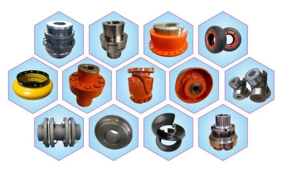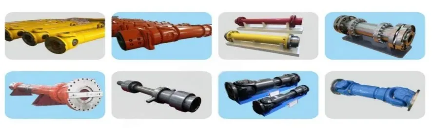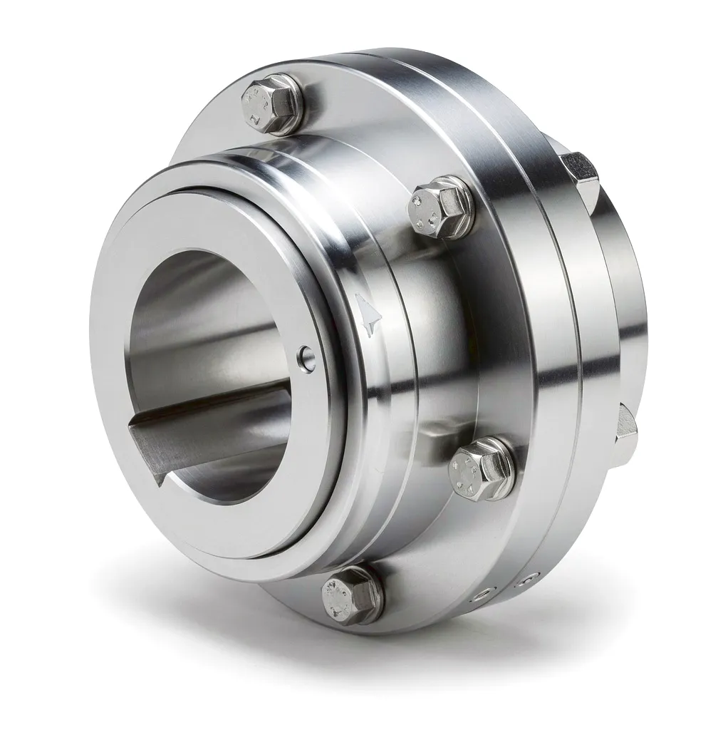
Application Scenario · Thermal Power Generation

Couplings in Thermal Power Generation: Engineering the Heart of Britain’s Energy Grid

High-performance coupling solutions for steam turbine–generator drives in coal-fired, gas-fired, and biomass power stations across the United Kingdom.

100,000+ Hour Service Life
G2.5 Dynamic Balance
Thermal Misalignment Compensation

Industrial coupling for thermal power plant application

Thermal power generation remains one of the most mechanically demanding environments in all of British industry. In stations operating across Yorkshire, the East Midlands, and Wales — whether burning pulverised coal, natural gas, or processed biomass — the drive train connecting a steam turbine to its generator represents one of the single most critical mechanical interfaces in the entire plant. A coupling failure at this juncture does not merely interrupt production; it can cascade into weeks of costly downtime, grid instability penalties under UK National Grid ESO balancing agreements, and in the worst case, serious equipment damage running to millions of pounds in replacement costs.

The role of the coupling in this environment is deceptively simple in concept yet extraordinarily demanding in practice. It must transmit hundreds of megawatts of mechanical power across the shaft interface, tolerate shaft misalignment arising from thermal expansion, absorb torsional shocks during grid synchronisation events, and do all of this continuously for service cycles measured not in months but in decades. Understanding why specific coupling types are specified for turbine–generator drives — and what engineering properties make them fit for purpose in a UK power station environment — is the starting point for any procurement or maintenance engineering decision in this sector.

This article explores the mechanical principles, material science, performance specifications, and real-world application contexts that define coupling selection for thermal power generation, with particular attention to the conditions found in the United Kingdom’s operating fleet of gas-fired combined cycle plants, older coal-to-gas conversion stations, and the growing biomass sector centred on sites such as Drax in North Yorkshire.

Working Principle: How Couplings Function in High-Speed Turbine Drives

At its core, a coupling in a thermal power application functions as a torque transmission bridge between two rotating shafts — the output shaft of the steam or gas turbine and the input shaft of the electrical generator. In a typical large UK combined cycle gas turbine (CCGT) plant, the turbine shaft rotates at 3,000 rpm to match the 50 Hz grid frequency directly, while in steam turbine installations, gearboxes may be interposed for intermediate speed reduction. In either case, the coupling must transmit the full rated torque reliably without introducing parasitic losses, vibration, or dynamic instability into either machine.

The dominant coupling type specified for this duty in the UK power sector is the gear coupling, though disc-pack and diaphragm couplings have gained significant market share in modern installations due to their oil-free maintenance profiles. A gear coupling achieves angular and axial misalignment compensation through the crowned tooth geometry of its gear mesh: the external teeth of the hub mesh with the internal teeth of the sleeve, and the crown profile of each external tooth permits small angular deflections without generating unacceptable tooth edge loading. This is precisely the mechanism that accommodates turbine shaft displacement caused by thermal growth during start-up and operation.

During a cold start — which is a routine event for peaking gas turbines at sites in the East Midlands that follow daily demand cycles — the turbine casing and shaft elongate by several millimetres relative to their cold positions as metal temperatures rise from ambient to operating levels above 500°C. Without misalignment-compensating capacity, this thermal expansion would impose severe bending loads on both machine bearing housings, accelerating wear and ultimately causing shaft seal failure. The coupling absorbs this differential movement silently, maintaining alignment within acceptable bearing load limits throughout the transient.
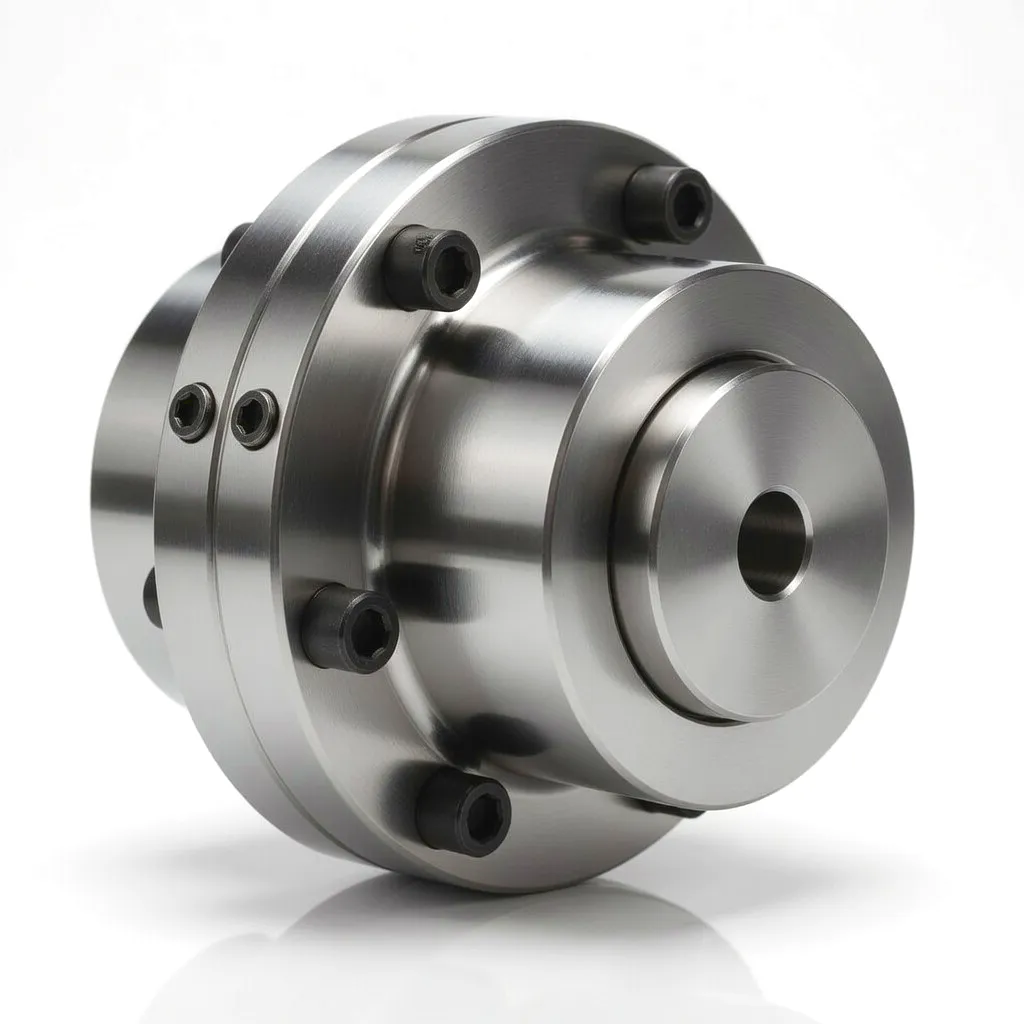
Gear coupling cross-section for power plant turbine drive

Key Functional Requirements

  • Torsional stiffness within G2.5 dynamic balance spec
  • Misalignment capacity ≥ 0.5° angular, ±3 mm axial
  • Zero backlash during normal synchronous running
  • Fail-safe under sudden load rejection events
  • Compatible with oil mist or dry lubrication systems
  • Full traceability to EN/BS material standards

Core Materials: Engineering Alloys for Extreme Duty in Power Station Environments
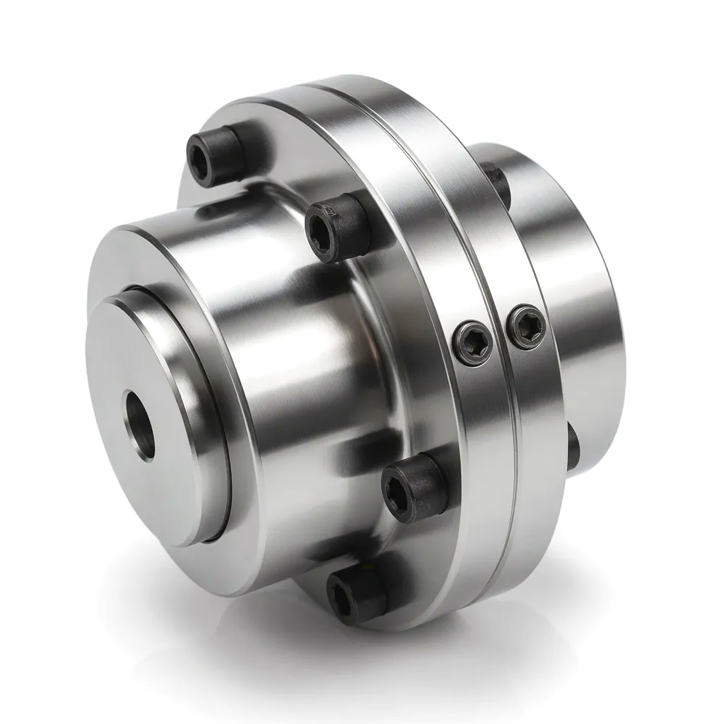
Coupling material metallurgy for power generation

The material selection for power station couplings is governed by a convergence of mechanical, thermal, and regulatory demands. In the UK, operators such as those holding generation licences under Ofgem regulation are required to demonstrate component traceability through certified material test reports (CMTRs), meaning that the base materials, heat treatment records, and non-destructive testing results must be documented and retained throughout the service life of the plant.

For gear coupling hubs, the overwhelming choice is alloy steel in the 42CrMo4 or equivalent AISI 4140 specification, through-hardened to 28–34 HRC. This grade delivers the combination of tensile strength (typically 900–1,100 MPa UTS), toughness at low-temperature start-up conditions, and resistance to the fretting fatigue that arises at the spline or interference-fit hub–shaft interface during cyclic load variation. For high-temperature zones where the coupling may be exposed to radiant heat from turbine casings, the hub flanges may be manufactured from 40CrNiMoA steel with improved creep resistance characteristics.

Coupling sleeves — which in a gear coupling carry the internal ring gear — are typically forged from the same 42CrMo4 grade, with tooth surfaces carburised and hardened to 58–62 HRC to resist the wear arising from the relative angular motion in the mesh under load. In disc-pack and diaphragm coupling configurations, the flexible elements themselves are manufactured from precipitation-hardened stainless steels such as 17-4PH or 15-5PH, which combine the corrosion resistance needed in humid turbine hall environments with the fatigue endurance required to survive tens of millions of flex cycles over plant life.

42CrMo4 Alloy Steel

Hub & sleeve forgings. UTS 900–1,100 MPa. Through-hardened 28–34 HRC. BS EN 10083 compliant.

Carburised Gear Surface

Tooth face hardness 58–62 HRC. Case depth 0.8–1.2 mm. Provides wear resistance in angular mesh motion.

17-4PH Stainless Steel

Disc-pack flex elements. Yield 1,000 MPa. Corrosion-resistant. Fatigue endurance for 10^8+ cycles.

40CrNiMoA Heat-Resistant Grade

High-temp flanges near turbine casings. Enhanced creep resistance up to 400°C service temperature.

Product Advantages: Why Power Station Engineers Specify These Couplings

Superior Misalignment Compensation

Gear and diaphragm couplings routinely accommodate angular misalignment of 0.5° to 1.5° and axial movement of ±3 to ±8 mm. In a 600 MW turbine unit at a station such as Cottam or West Burton, thermal growth of the turbine shaft between cold and hot conditions can reach 6–8 mm. Couplings with adequate axial float absorb this entirely without imposing thrust loads on generator or turbine bearings, extending bearing overhaul intervals significantly.

🔥

Outstanding Fatigue Life

The most demanding requirement in continuous baseload duty is cumulative fatigue endurance. Couplings specified for large generator drives are engineered to exceed 100,000 hours of service life — equivalent to over 11 years of around-the-clock operation — without requiring replacement of core components. Torsional fatigue analysis in accordance with ISO 10441 is conducted as part of the design validation, ensuring that tooth root stresses remain below the endurance limit under all load combinations.

Precision Dynamic Balance to G2.5

Rotating at 3,000 rpm in a 50 Hz synchronous machine, even modest residual unbalance in a coupling creates significant centrifugal forces that manifest as vibration measured on the machine casing. UK power station operators routinely specify G2.5 balancing grade in accordance with ISO 1940-1, requiring residual specific unbalance below 2.5 g·mm/kg. For very large generator couplings above 1,000 kg, this demands meticulous single-plane and two-plane balance correction after final assembly, performed on high-speed dynamic balancing machines.

👥

Torsional Shock Absorption

Grid disturbances — including voltage dips, nearby fault clearances, and generator pole-slipping events — generate intense torsional transients in the rotor train. These transients, if unchecked, impose peak torques several times the rated value on coupling elements. Properly designed diaphragm and disc couplings integrate torsional compliance in their flex elements, limiting peak dynamic torque transmitted to the generator shaft and protecting against crankshaft-type fatigue cracking that has historically caused catastrophic failures in older installations.

📋

Reduced Maintenance Burden

Modern disc and diaphragm coupling designs eliminate the lubrication requirement that has historically been the main maintenance task associated with gear couplings in UK power stations. Oil-lubricated gear couplings require annual oil changes plus periodic inspection of oil seals, whereas maintenance-free flex-element couplings need only visual inspection during planned outages. For UK generators operating under capacity market agreements where availability penalties are substantial, this reduction in scheduled maintenance events directly improves the annual availability factor and revenue performance.

🔧

Full Standards Compliance

Power station couplings supplied into the UK market are designed and manufactured in compliance with relevant international and British standards including ISO 10441 (flexible couplings for petroleum, chemical, and gas industry services), ISO 1940-1 (balancing quality), and EN 10083 (alloy steel specifications). Full documentation packages including design calculations, material certificates, inspection records, and dynamic balance reports are provided as standard, satisfying both the technical and audit requirements of UK power station operations teams.

Technical & Performance Parameters: Coupling Specifications for Thermal Power Generation

พารามิเตอร์ข้อต่อเกียร์ข้อต่อดิสก์Diaphragm Coupling
Rated Torque Range500 Nm – 5,000 kNm200 Nm – 2,000 kNm1,000 Nm – 3,000 kNm
Maximum Speed (rpm)Up to 10,000Up to 15,000Up to 12,000
การเยื้องศูนย์เชิงมุมสูงสุด 1.5°Up to 1.0°Up to 0.5°
Axial Movement±3 to ±8 mm±1 to ±5 mm±2 to ±6 mm
Hub Material42CrMo4 / 40CrNiMoA42CrMo4 alloy steel42CrMo4 alloy steel
Flex Element MaterialCase-hardened 42CrMo417-4PH / 15-5PH SS17-4PH stainless steel
Balancing GradeG2.5 (ISO 1940-1)G2.5 or betterG2.5 or better
อุณหภูมิในการให้บริการ-30°C to +150°C-60°C to +300°C-60°C to +350°C
Design Service Life> 100,000 hours> 100,000 hours> 100,000 hours
LubricationOil or grease requiredMaintenance-freeMaintenance-free
Applicable StandardISO 10441ISO 10441 / API 671API 671

Application Scenario 13

Steam Turbine–Generator Drive in Thermal Power Generation Units

Thermal power plant coupling application

Within a thermal power station — whether that plant burns natural gas in a combined cycle configuration, coal in a traditional Rankine cycle arrangement, or biomass pellets as part of the UK’s renewable obligations programme — the mechanical connection between the prime mover and the electrical generator is the single highest-stakes transmission point in the entire drive train. In a large generating unit rated at 400–660 MW, such as those that formed the backbone of England’s generation fleet at sites including Cottam, Ratcliffe-on-Soar, and West Burton before progressive decommissioning began in the mid-2010s, this coupling transmits torques in the range of 1,000 to 2,500 kNm continuously at shaft speeds of 3,000 rpm.

The thermal growth challenge in this application is not trivial. A large steam turbine’s rotor, manufactured from creep-resistant Cr-Mo-V alloy steel, undergoes axial elongation of several millimetres between its cold and hot states as it absorbs steam energy and reaches thermal equilibrium at operating temperatures in excess of 500°C. The coupling positioned at the low-pressure turbine exhaust end — typically the point of connection to the generator — must accommodate this growth without restraining the turbine casing or imposing excessive thrust into the generator’s thrust bearing. In gear coupling designs used at British power stations, this is achieved through a floating shaft arrangement in which axial freedom is built into the gear mesh geometry.

Power generation coupling installation turbine hall UK

In modern CCGT plants operating throughout England and Scotland — with major facilities in North Yorkshire, Lincolnshire, and the Firth of Forth corridor — the challenge is somewhat different but no less demanding. Gas turbines coupled to high-speed generators in a single-shaft CCGT arrangement may rotate at speeds above 3,000 rpm, requiring gearboxes to achieve grid-synchronous speed. In these configurations, the coupling between gas turbine and gearbox input shaft must handle not only rated torque but also severe torsional excitations arising from the periodic ignition events within the combustion chambers. Each firing stroke in a gas turbine produces a measurable torque ripple that, at certain rotor speeds, can excite torsional natural frequencies in the shaft system if not properly accounted for in the coupling’s torsional compliance design.

The United Kingdom’s growing biomass power sector, centred most prominently on the Drax Power Station in North Yorkshire — now converted entirely to biomass from its original coal-fired configuration and representing one of the largest biomass generation facilities in the world — presents its own unique demands. Biomass plants experience more frequent start–stop cycling than traditional baseload coal plants, as they participate actively in balancing markets and respond to renewable energy dispatch patterns. This higher cycling frequency means the coupling accumulates more thermal transient cycles per year, placing greater emphasis on fatigue life in the thermal gradient zone rather than simple steady-state endurance. Couplings for this duty are therefore designed with higher safety factors against fatigue cracking near the hub keyway regions.

Operating Context — UK Thermal Fleet

Operating Speed

3,000 rpm

50 Hz synchronous UK grid

Peak Torque Range

1,000–2,500 kNm

400–660 MW unit class

Thermal Shaft Growth

6–8 mm

Cold to hot differential

Required Service Life

> 100,000 h

Continuous baseload duty


Further Industrial Application Scenarios: Coupling Performance Across Critical UK Industries

Application Scenario

Wind Farm Gearbox Drives — UK Offshore

Offshore wind turbines operating across the North Sea and in the Irish Sea — at arrays including Hornsea One, Dudgeon, and Beatrice — subject their drive train couplings to a uniquely punishing combination of variable torque loading from wind gusts, continuous vibration from wave action on the monopile foundation, and corrosive marine atmosphere. Couplings at the main shaft-to-gearbox interface and at the gearbox-to-generator connection must accommodate the significant angular misalignment that occurs as the nacelle flexes under aerodynamic loading, while simultaneously resisting the salt fog that penetrates even well-sealed nacelle enclosures.

Application Scenario

Steel Rolling Mill Drives — Sheffield & Rotherham

The steel industry in South Yorkshire, centred on Sheffield and Rotherham, represents one of the oldest and most demanding industrial environments for drive couplings in the United Kingdom. Rolling mill main drives subject couplings to severe torsional impulse loads each time a steel billet enters the roll gap. At the moment of bite, the rolling force surges abruptly, creating a sharp torque spike that can reach three to five times the steady-state value. Couplings for this duty require very high peak torque capacity, robust construction to withstand millions of such impulse cycles over the mill’s operating life, and the ability to accommodate the misalignment arising from thermal growth of the mill housing under the substantial heat generated during hot rolling.

Application Scenario

Pump Drives in Water Treatment — Birmingham & Midlands

Severn Trent Water and other Midlands water utilities operate extensive networks of pumping stations across the Birmingham and West Midlands region, handling raw water abstraction from the Severn and Trent river systems as well as final distribution pressurisation. Large centrifugal pumps in these installations are driven by electric motors through flexible couplings, and the demands placed on the coupling include the classic water utility requirements: resistance to the humid, occasionally chemically contaminated atmosphere of a pump house, accommodation of the thermal growth differential between motor and pump shaft systems, and the capacity to survive the hydraulic shock loads that occur during valve closure or pump trip events.

Application Scenario

Marine Propulsion Gearboxes — UK Shipbuilding

British shipyards, including those operating on the Clyde in Scotland and BAE Systems’ facilities on the south coast, specify high-integrity couplings for naval vessel propulsion systems. In this context, the coupling between the diesel engine or gas turbine prime mover and the propulsion gearbox must handle not only the full rated power of engines that may deliver several thousand kilowatts, but also the torsional shock loads arising from propeller cavitation events, blade entry into surface wave disturbed water, and emergency astern operations. Naval specifications add further demands around acoustic signature, requiring that the coupling transmit no vibration harmonics that could compromise the vessel’s sonar signature or be detectable by passive acoustic sensors.

Our Coupling Product Range

Flexible Beam Coupling product

ข้อต่อคานแบบยืดหยุ่น

A compact, maintenance-free solution ideal for servo motor and precision instrument drives. The helical beam geometry provides torsional compliance while maintaining zero backlash, making it the preferred choice for encoders, stepper motor drives, and laboratory automation systems. Manufactured from high-strength aluminium alloy or stainless steel depending on bore diameter and torque requirements.

View Product →

Disc Coupling product

ข้อต่อดิสก์

The disc coupling represents the state of the art in high-torque, maintenance-free power transmission for turbine generator drives, compressor trains, and high-speed rotating machinery. Stainless steel disc packs accommodate angular and axial misalignment through elastic deformation of the disc profile, transmitting torque with torsional stiffness that is significantly higher than elastomeric alternatives while generating zero friction and requiring no lubrication. Available in single-disc and double-disc configurations depending on the degree of misalignment compensation required.

View Product →

Manufacturing Excellence

Ever Power: Precision Coupling Manufacturing & Customisation for the UK Power Sector

Ever Power operates a dedicated manufacturing facility equipped with advanced CNC turning, grinding, and gear cutting centres, producing couplings for the most demanding applications in thermal power generation, oil and gas processing, and heavy industry. Our in-house metallurgical capability allows us to procure, validate, and process alloy steel billets through the complete production chain — from raw material incoming inspection against EN 10083 material certificates, through forge quality control, heat treatment supervision, precision machining to ISO 286 tolerance grades, and final dynamic balancing on high-speed balancing machines calibrated to ISO 1940-1 standards.

Our customisation service is genuinely comprehensive. When a UK power station engineering team approaches Ever Power with a replacement coupling requirement for a turbine generator drive, our application engineering team begins with a detailed review of the existing shaft geometry, operating speed, torque envelope including peak load events, misalignment history from previous service records, and the maintenance interval philosophy of the plant operator. From this information, we develop a coupling design that may be a direct dimensional replacement for the existing component, or may incorporate engineering improvements — such as converting from a lubricated gear coupling to a maintenance-free disc pack configuration — that reduce the total cost of ownership over the remaining plant life.

Ever Power’s supply chain management ensures that critical deliveries to UK power stations — where planned outage windows are measured in days and delays carry significant financial penalties under availability contracts — are met reliably. We maintain strategic stocks of semi-finished coupling hubs in the most common diameter ranges, enabling rapid lead times for urgent replacement orders. Our documentation capability includes the full CMTR traceability package required by UK power generation operators, compiled into a single handover document set that satisfies both maintenance records and insurance inspection requirements.
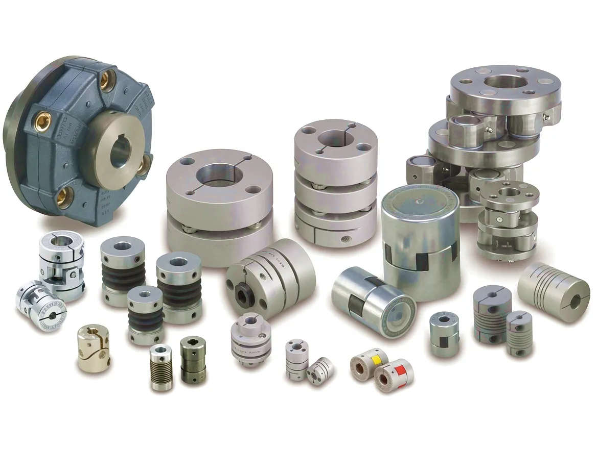
Ever Power coupling manufacturing facility

🏠

In-House Forge & Machine

Complete vertical integration

📋

Full CMTR Documentation

BS EN 10083 material traceability

G2.5 Balance Certification

ISO 1940-1 compliant test reports

👥

Custom Bore & Keyway

To customer shaft drawings

Customer Success Story: Drax Group — North Yorkshire Biomass Station Coupling Upgrade

ที่ตั้ง

Selby, North Yorkshire

Sector

Biomass Power Generation

Unit Output

660 MW

ท้าทาย

Coupling Replacement

Power generation application coupling installation

The engineering team at a major biomass power generation site in Selby, North Yorkshire, approached Ever Power during the 2024 planned outage season with a pressing requirement: one of their 660 MW steam turbine units had developed progressive vibration issues traced through vibration monitoring analysis to deterioration of the turbine–generator coupling. The existing gear coupling, which had accumulated approximately 85,000 operating hours since its last major overhaul, was exhibiting elevated vibration signatures at twice-running-speed frequency — a classic indicator of coupling angular misalignment accumulation combined with tooth wear reducing the contact ratio in the gear mesh.

The challenge was compounded by the station’s cycling profile: converted from coal to biomass operation, this unit now participated heavily in the UK capacity market and responded regularly to National Grid ESO dispatch instructions, experiencing significantly more start–stop cycles per year than it had during its original baseload coal-burning service life. The engineering team recognised that a like-for-like gear coupling replacement, while straightforward, would reproduce the same maintenance demands that had contributed to the current degraded condition. They asked Ever Power to evaluate the feasibility of upgrading to a maintenance-free disc coupling configuration.

Ever Power’s application engineering team conducted a full torsional analysis of the rotor train, working from shaft drawings and historical vibration data provided by the station. The analysis confirmed that the proposed disc coupling configuration would maintain adequate torsional compliance while achieving a significant improvement in balance quality. The custom disc coupling was manufactured, assembled, dynamically balanced to G2.5, and delivered within the planned outage window. Post-installation vibration measurements confirmed a reduction in overall shaft vibration amplitude exceeding 40%, with both turbine and generator bearing housings now operating comfortably within the plant’s operating guidelines.

What Our Clients Say

★★★★★

“The disc coupling Ever Power supplied for our turbine–generator interface has delivered exactly what their application team promised — vibration levels have dropped significantly, and we’ve completely eliminated the annual coupling oil service that used to consume two man-days of outage time. The documentation pack was thorough and sailed through our QA audit.”

J

James H., Senior Mechanical Engineer

Biomass Power Station, North Yorkshire

★★★★★

“What sets Ever Power apart is their willingness to actually engage with the application before quoting a standard product. Their engineers understood the torsional implications of our cycling duty, and the coupling they designed reflected that understanding. We’re now three years and approximately 6,000 additional operating hours into the service life of this coupling without any issues whatsoever.”

R

Rachel T., Plant Engineering Manager

CCGT Power Station, East Midlands

★★★★★

“We had a tight outage window — 14 days for the full planned inspection — and Ever Power delivered the custom balanced coupling assembly within that schedule. The G2.5 balance certificate was included, and the unit returned to service with vibration readings that our monitoring system flagged as the lowest ever recorded on that bearing position. Genuinely impressive manufacturing quality.”

M

Michael D., Maintenance Contracts Director

Independent Power Producer, West Yorkshire

 

Ready to Discuss Your Application?

Industrial coupling application environmentPower Station Coupling Solutions Delivered On Schedule

Ever Power application engineers are available to review your drive train specifications and provide a no-obligation coupling recommendation with indicative pricing.

✉ Contact Ever Power Engineering

คำถามที่พบบ่อย

+
How do I choose the right type of coupling for a steam turbine generator in a UK thermal power station?
Selecting the right coupling for a steam turbine–generator drive in a UK power station requires evaluating several intersecting factors: the rated and peak torque at the coupling face, the shaft operating speed relative to the electrical grid frequency of 50 Hz, the degree of shaft misalignment arising from thermal growth during start-up, and the maintenance interval philosophy of the plant operator. Gear couplings suit applications where very high torque capacity and significant axial float are the priority. Disc couplings are preferred where maintenance-free operation and high torsional stiffness are paramount, particularly in combined cycle plants where lubrication of gear tooth meshes is difficult to manage reliably. Ever Power’s engineering team can review your specific drive train data and make a recommended specification.
+
What is the typical price or cost of a custom turbine generator coupling from a UK industrial supplier like Ever Power?
The cost of a custom turbine–generator coupling varies considerably depending on the rated torque, shaft bore diameters, coupling type (gear, disc, or diaphragm), material specification, and the documentation and testing scope required. For a large power station coupling in the 500–2,500 kNm torque range, with full CMTR traceability, NDT certification, and dynamic balance to G2.5, indicative pricing typically reflects the high-quality materials, precision machining, and extensive quality assurance involved. The best way to obtain accurate pricing is to request a quote from Ever Power by email at [email protected], providing your shaft dimensional requirements, operating speed, and torque envelope.
+
Which coupling type is best suited for high-speed biomass power plant drives operating at 3,000 rpm in North Yorkshire?
For biomass power generation at a 50 Hz synchronous speed of 3,000 rpm, disc couplings represent the preferred modern solution where maintenance-free operation is the priority. Biomass plants such as those in North Yorkshire experience more frequent cycling than traditional baseload coal stations, which increases the number of thermal transient cycles per year and accelerates wear in lubricated gear coupling meshes. A disc coupling with 17-4PH stainless steel flex elements eliminates this wear mechanism entirely while maintaining the high torsional stiffness that limits vibration amplitude at synchronous running speed. For drives where very large axial float is required to accommodate significant turbine thermal growth, a gear coupling with adequate axial travel in the tooth mesh remains a valid and proven alternative.
+
How long does it take to get a replacement coupling delivered to a power station in the UK, and can you meet tight outage windows?
Ever Power understands that UK power station planned outages operate on fixed schedules with significant financial implications for overruns. For replacement couplings where dimensional details are provided promptly, our standard delivery timeframe for custom-manufactured turbine generator couplings — including machining, heat treatment, NDT, final assembly, and dynamic balancing — is typically 6 to 10 weeks from receipt of confirmed order and drawings. Where there is an emergency requirement during an unplanned outage, our team will assess the feasibility of expedited manufacture and advise on realistic lead times. We maintain semi-finished hub stock in common diameter ranges that can reduce lead times for urgent replacements. Contact us at [email protected] to discuss your specific timeline.
+
Where can I find a reliable coupling supplier in the UK who can provide ISO 10441 compliant documentation for a power station application?
Finding a coupling supplier with genuine ISO 10441 compliance and full documentation capability is a critical step in procuring a turbine generator coupling for a UK power station. ISO 10441 covers flexible couplings for petroleum, chemical, and gas industry services but is widely applied as the governing standard in power generation applications as well. A compliant supplier should be able to provide design calculations, material test certificates to EN 10083 or equivalent, non-destructive test records (UT and MT as applicable), dynamic balance test reports to ISO 1940-1, dimensional inspection reports, and an assembly completion certificate. Ever Power provides all of these documents as a standard part of our quality documentation package for power station couplings. Contact our sales team to request a documentation scope confirmation before placing an order.
+
What causes coupling vibration problems in a CCGT plant, and how can upgrading to a disc coupling help resolve them?
Coupling-related vibration in a combined cycle gas turbine plant typically manifests as elevated once-per-revolution or twice-per-revolution vibration amplitude at the bearing housings adjacent to the coupling, visible on the plant’s continuous vibration monitoring system. The most common root causes are progressive tooth wear in a gear coupling leading to increased angular play in the mesh, lubricant degradation reducing the hydrodynamic film thickness in the tooth contact zone, or coupling mass unbalance developing as a result of corrosion or material loss. Upgrading to a disc coupling eliminates the tooth mesh entirely, replacing it with an elastic flex element that operates without wear, without lubrication, and with balance characteristics that are inherently more stable over time. The conversion typically results in a measurable and sustained reduction in bearing housing vibration amplitude that can extend the overhaul interval for both turbine and generator bearings.
+
When should I schedule a coupling inspection at my Birmingham or East Midlands power plant to avoid unplanned outages?
Coupling inspection in a thermal power plant is most effectively scheduled as part of the planned major overhaul cycle, which for most UK gas-fired and biomass stations occurs at intervals of 4–6 years or based on accumulated operating hours in accordance with the Original Equipment Manufacturer’s maintenance schedule for the turbine and generator. However, continuous vibration monitoring provides the most reliable early indicator of developing coupling deterioration between scheduled outages. An increasing trend in once-per-revolution vibration amplitude, or the emergence of distinctive twice-per-revolution content in a gear coupling application, should prompt earlier inspection. Plants in the East Midlands and West Midlands that are now cycling more frequently due to market dispatch patterns should consider reducing their coupling inspection interval proportionally, as cycling accelerates certain degradation mechanisms regardless of total operating hours.

© Ever Power Industrial Couplings | gear-type-coupling.top | [email protected]

แก้ไขโดย gzl