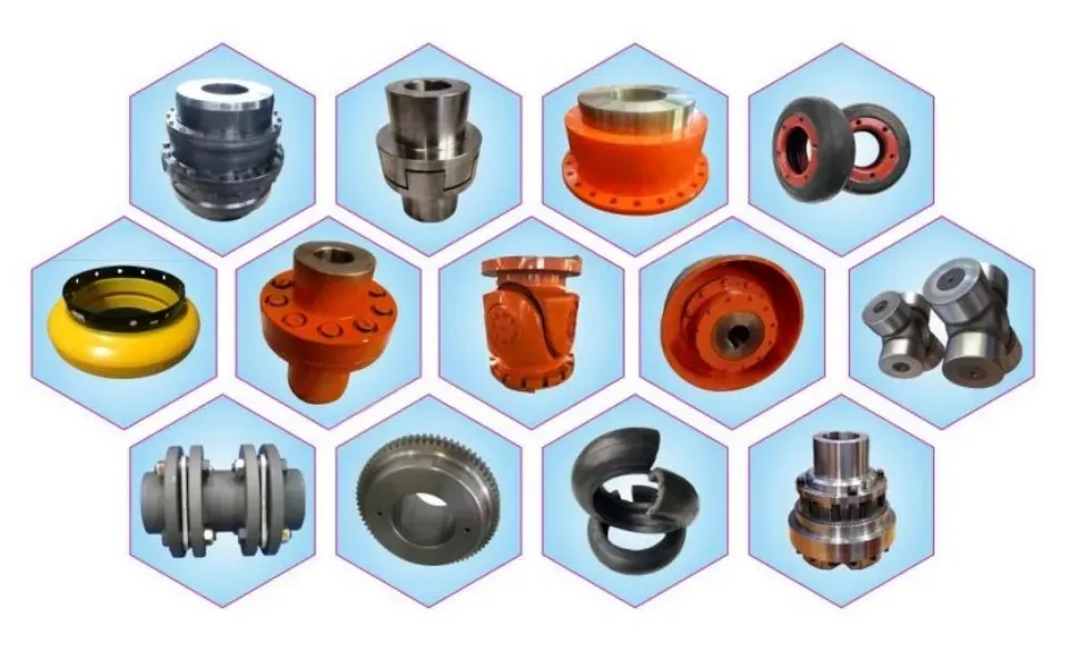
Industrial Power Transmission | Cement Industry
Koppelingen voor cementdraaiovens: De aandrijving die nooit stopt
How the right coupling selection protects rotary kiln drives from misalignment, thermal shock, and continuous heavy-load fatigue — a deep engineering guide for UK cement and building materials manufacturers.
Torque: up to 500,000 N·m
Doorlopende dienst
High-Temperature Rated
UK Market Ready
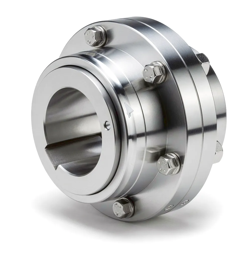
The cement rotary kiln is one of the most mechanically demanding installations in British heavy industry. Stretching anywhere from 50 to 200 metres in length and rotating continuously under enormous thermal and mechanical loads, these kilns process limestone and other raw materials at temperatures exceeding 1,400 degrees Celsius. The drive system responsible for keeping the kiln turning — even as its shell flexes, its axis drifts with thermal expansion, and its load surges during clinker formation — is under constant, relentless stress. At the very heart of that drive system sits the coupling, an engineering component whose seemingly modest role disguises extraordinary criticality. A coupling failure on a cement kiln means a full production shutdown: lost output, emergency maintenance costs, and in facilities serving UK construction supply chains, penalties that reach into tens of thousands of pounds per day of unplanned downtime.
Unlike simpler rotating machinery where a coupling merely transmits torque from shaft A to shaft B, the coupling on a cement rotary kiln must simultaneously handle angular misalignment caused by kiln shell creep, radial offset introduced by thermal expansion of the support rollers, and axial movement as the kiln migrates along its axis during operation. It must absorb periodic torque shocks when cold feed material drops into a hot zone, and it must do all of this continuously — 24 hours a day, 365 days a year — in a dust-laden, high-vibration environment where lubrication intervals may stretch to months. Understanding exactly what type of coupling meets these demands, and why the metallurgical and geometric design choices matter, is fundamental to anyone specifying or maintaining kiln drives in the UK cement and lime-burning sectors.
The Mechanical Reality of Cement Rotary Kiln Drives
Why standard couplings simply do not survive in this environment
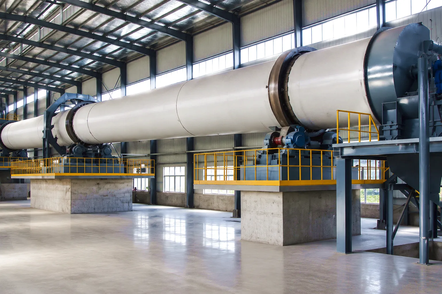
A typical cement rotary kiln drive in the UK — whether at a facility in the West Midlands, in the limestone quarry districts around Buxton, Derbyshire, or at coastal import grinding stations near Portland — operates through a motor and reducer assembly that transmits torque through a gear coupling or a similarly rated flexible coupling to the kiln’s main gear ring. The drive must produce enough torque to overcome the inertia of a shell that may weigh several hundred tonnes when loaded, start reliably even in winter conditions when lubrication is cold and viscous, and maintain smooth rotational output through the full range of kiln loading conditions.
What distinguishes this application from, say, a pump drive or a conveyor drive, is the combination of factors acting simultaneously. The kiln shell runs on two or three sets of support rollers, and as the shell heats up from ambient temperature to operating temperature — a difference that can exceed 300 degrees Celsius at the shell surface — it expands both radially and axially. This thermal growth introduces shaft misalignment in the drive train that may not have existed at cold startup. On top of this, the kiln wobbles slightly as it rotates, because no kiln shell is perfectly round along its full length, and this periodic runout generates cyclic radial loads on the coupling. The coupling must accommodate all these dynamic offsets without transmitting damaging reaction forces back into the gearbox or motor bearings.
British cement producers operating under tight energy efficiency targets — driven in part by the UK industrial decarbonisation agenda — are also increasingly sensitive to coupling power loss. Every percentage point of mechanical transmission efficiency that can be recovered through better coupling design reduces kiln operating costs and lowers the carbon intensity of clinker production. The engineering choice of coupling is therefore both a reliability decision and an energy efficiency decision.
300°C
Shell Temp Differential
Working Principle: How Gear Couplings Manage Kiln Drive Loads
The mechanics behind misalignment accommodation and torque transmission
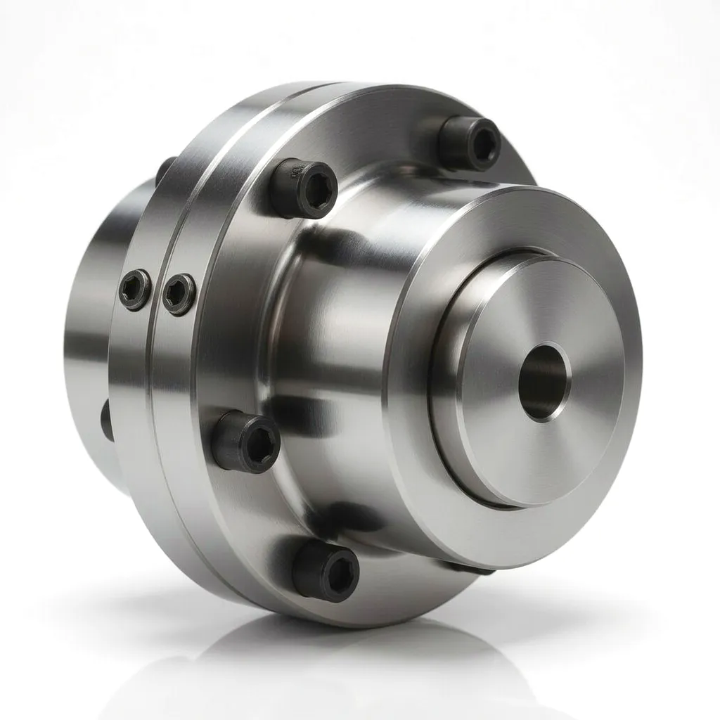
The gear coupling — the dominant choice for cement rotary kiln main drives — operates on the principle of crowned gear tooth engagement between two internal gear sleeves and two external gear hubs. Each hub is mounted on one shaft end, while the sleeve assembly bridges the two hubs. The crowning of the gear teeth, meaning the deliberate convex profiling of each tooth along its face width, is the geometric feature that makes misalignment accommodation possible. When the two shafts are not perfectly collinear — which in a kiln drive is virtually always the case — the crowned teeth rock against the sleeve teeth through a small arc, tilting the engagement contact zone without generating the catastrophic edge loading that would occur with straight-tooth gears under the same conditions. This tooth geometry, combined with a continuous film of heavy lubricant between mating surfaces, allows the coupling to maintain full torque capacity even as the misalignment changes dynamically during kiln rotation.
Torque is transmitted through the shear stress in the lubricant film and direct tooth-to-tooth contact across multiple simultaneously engaged teeth, distributing the enormous torque loads that a kiln drive produces. At full production speed, a modern wet-process kiln drive may develop sustained torques of 200,000 to 500,000 N·m at the coupling, with momentary peak loads during startup or feed surges reaching 2.5 to 3 times nominal torque. The coupling must transmit these peak loads without tooth stripping, sleeve cracking, or flange bolt failure, returning smoothly to steady-state operation without leaving residual damage in the gear mesh.
Key Operating Principles
01Crowned tooth geometry accommodates angular and radial offset
02Multi-tooth engagement spreads load across the gear mesh
03Grease-sealed or oil-bath lubrication prevents micro-welding under slip
04Floating spacer shaft allows removal without moving drive components
The axial accommodation capability of a gear coupling in kiln service is equally important. Cement kilns migrate up and down their inclination axis as thermal conditions change throughout the day and across seasonal temperature swings that can vary by 20 to 30 degrees Celsius in exposed UK locations. This axial travel — which may total 20 to 50 mm on a large kiln — would snap a rigid coupling instantly, but a gear coupling simply slides the sleeve along the hub teeth to absorb the movement. The teeth act as splines in the axial direction, transmitting torque while simultaneously permitting shaft travel without generating thrust loads that the gearbox output bearing was never designed to carry. It is this multidimensional compliance — angular, radial, and axial simultaneously — that makes the gear coupling the engineering benchmark for cement kiln main drives throughout UK and European heavy industry.
Core Materials: What Keeps Kiln Drive Couplings Alive
Metallurgical and material science behind long-service kiln couplings
⚙
Alloy Steel Hubs (42CrMo4)
The gear hubs of kiln-duty couplings are manufactured from quenched-and-tempered chromium-molybdenum alloy steel, typically conforming to 42CrMo4 or AISI 4140 specifications. This alloy delivers a tensile strength of 900 to 1,100 MPa after heat treatment, with a Brinell hardness of 250 to 300 HB, providing the tooth root strength needed to survive peak torque events without plastic deformation. The alloy’s molybdenum content contributes to deep hardenability, ensuring that the beneficial hardening extends well into the tooth cross-section rather than just the surface layer.
🛠
Carburised & Case-Hardened Teeth
The gear teeth themselves undergo carburising followed by controlled quenching to produce a hardened case depth of 0.8 to 1.5 mm, with surface hardness reaching 58 to 62 HRC. This hardened case resists the abrasive micro-sliding that occurs between crowned teeth during misalignment compensation, a wear mechanism that destroys unhardened couplings within months in kiln service. The retained austenite content is controlled to below 15% to prevent progressive softening under operational heat cycling, which would reduce the wear resistance and allow fatigue cracks to propagate from the hardened surface into the softer core.
💧
High-Viscosity Extreme-Pressure Lubricant
The lubricant retained within the coupling sleeve cavity is not a standard industrial grease. Kiln-duty couplings require a high-viscosity, extreme-pressure grease formulated with lithium complex or polyurea thickeners and EP (extreme pressure) additives such as sulphur-phosphorus compounds. The grease must resist centrifugal separation at typical kiln coupling peripheral speeds of 3 to 8 m/s, must not oxidise or harden under the heat radiated from the kiln shell, and must maintain its film strength under the oscillating contact loads imposed by misalignment compensation. Grease relubrication intervals on well-sealed kiln couplings typically range from 6 to 18 months, a significant operational advantage in facilities like those serving Sheffield’s construction material supply chains where maintenance windows are tightly scheduled.
🧰
Forged Steel Flanged Sleeves
The outer sleeves are die-forged from medium carbon steel, stress-relieved after machining to eliminate residual manufacturing stresses that could initiate fatigue cracks during heavy cyclic loading. The bolted flange joint connecting the two sleeve halves uses high-tensile bolts tightened to precise preload specifications, creating a friction-coupled joint that transmits part of the torque in addition to the gear mesh. On large kiln couplings, these flange bolts may be metric M48 or M56 grade 12.9, tightened with hydraulic bolt tensioners to preloads calculated to prevent relative slip between the flange faces under worst-case peak torque, including the transient overloads that occur during kiln start-up with a cold shell.
Product Advantages: Why Kiln Operators Choose Gear Couplings
Engineering advantages that reduce total cost of ownership in cement manufacturing
1
Simultaneous Three-Axis Misalignment Compensation
Unlike disc couplings that handle angular misalignment well but are stiffer in the radial direction, and unlike jaw couplings that absorb radial offset but struggle with combined misalignment, the gear coupling used in kiln drives handles angular, radial, and axial offsets simultaneously and continuously. This three-dimensional compliance maps precisely onto the misalignment profile of a real operating kiln, where all three offset types occur at once and change with load, temperature, and kiln rotational position.
2
Extremely High Torque Density
Gear couplings offer the highest torque-to-mass ratio of any coupling type suitable for kiln main drives. This high torque density means that the coupling itself remains a relatively compact and manageable component even at the enormous torque levels required by large kilns, avoiding the access and maintenance complications that would accompany a disproportionately large coupling housing. The compact form factor also reduces the rotational inertia added to the drive train by the coupling, which slightly eases motor startup loading.
3
Long Service Life and Predictable Wear Profile
A properly specified and maintained gear coupling in kiln service typically achieves 5 to 10 years of service before requiring replacement. This long service life dramatically reduces the total number of planned shutdowns required for coupling maintenance over a kiln’s operational lifetime. Furthermore, wear on gear coupling teeth progresses gradually and can be detected through lubricant analysis — monitoring the metal particle content and size distribution in used coupling grease gives advance warning of accelerating tooth wear, allowing the maintenance team to plan replacement during a scheduled kiln stop rather than responding to an emergency breakdown.
4
Overload Protection Through Tooth Slip
Under severe transient overload conditions — such as a kiln blockage, a feed surge that introduces excessive kiln loading, or a mechanical seizure elsewhere in the drive train — the gear coupling provides a degree of overload protection by allowing the gear teeth to slip at a predictable torque threshold before transmitting the full shock load to the gearbox or motor. While gear couplings are not torque limiters in the strict sense, this controlled slip capacity acts as a last-resort safeguard that can prevent catastrophic damage to far more expensive drive components under exceptional shock loading conditions.
5
Spacer Shaft Design for In-Situ Maintenance
Kiln drive coupling specifications almost always include a flanged spacer shaft between the two coupling halves. This spacer maintains the required distance between the gearbox output shaft and the kiln drive shaft, but its primary maintenance value is that it can be removed without disturbing either shaft, allowing inspection, relubrication, or replacement of the coupling elements without any need to move the gearbox or drive components. In a confined kiln drive pit, where access is already challenging, this spacer shaft maintainability reduces planned maintenance downtime by several hours compared to solid-hub coupling designs requiring shaft separation.
6
High Transmission Efficiency Under All Loading Conditions
With a properly maintained lubricant film, gear couplings achieve mechanical transmission efficiencies above 99% across the full torque range, a performance characteristic that meets the energy efficiency requirements now being prioritised by UK cement producers working within carbon reduction frameworks. The power loss in a gear coupling occurs primarily through viscous shear in the lubricant film during misalignment compensation, and this loss is small — typically less than 0.5% of transmitted power — even under the combined misalignment conditions encountered in kiln drives.
Technical Performance Parameters: Cement Rotary Kiln Coupling
Gear coupling specification ranges for cement kiln main drive and auxiliary drive applications
| Parameter | Auxiliary Drive | Medium Kiln Main Drive | Large Kiln Main Drive |
|---|
| Nominal Torque (T_n) | 5,000 – 30,000 N·m | 30,000 – 200,000 N·m | 200,000 – 500,000 N·m |
| Peak Torque Multiplier | x 2.5 | x 2.5 – 3.0 | x 2.5 – 3.0 |
| Hoekafwijkingscapaciteit | up to 2.5° | up to 2.0° | tot 1,5° |
| Radial Misalignment Capacity | up to 2.0 mm | up to 3.0 mm | up to 4.5 mm |
| Axial Displacement Range | +/- 5 mm | +/- 15 mm | +/- 30 mm |
| Maximale snelheid | up to 1,500 rpm | up to 750 rpm | up to 350 rpm |
| Naafmateriaal | 42CrMo4 Q+T | 42CrMo4 Q+T | 34CrNiMo6 Q+T |
| Tandoppervlaktehardheid | 58 – 62 HRC | 58 – 62 HRC | 58 – 62 HRC |
| Case Depth (Carburised) | 0.8 – 1.2 mm | 1.0 – 1.5 mm | 1.2 – 2.0 mm |
| Transmission Efficiency | greater than 99% | greater than 99% | greater than 99% |
| Smeertype | EP Grease (Grease-Packed) | EP Grease or Oil-Bath | Oil-Bath Preferred |
| Expected Service Life | 3 – 5 years | 5 – 8 years | 7 – 12 years |
Application Scenarios: Where Couplings Are Critical in Cement Rotary Kiln Systems
Specific coupling installation points within the cement production process
01
Application Scenario: Cement Rotary Kiln Main Gear Ring Drive
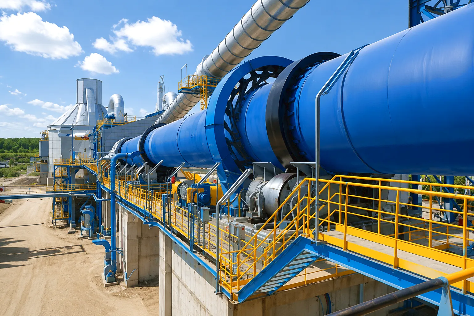 The most critical coupling position in any cement plant is between the main gearbox output shaft and the kiln’s main drive pinion shaft, which meshes with the large ring gear mounted on the kiln shell. This is where the full kiln drive torque passes — anywhere from 100,000 to 500,000 N·m on a production kiln — and where the combined misalignment from thermal expansion, shell deflection, and roller creep is at its most complex. The coupling here must operate without interruption for months at a time, often in an enclosed drive pit below floor level where ambient temperatures can reach 60 degrees Celsius due to heat radiation from the kiln shell above. Birmingham-based industrial equipment suppliers have long recognised this as the specification point where coupling quality has the greatest leverage on overall plant availability, since a failure here stops the entire kiln immediately.
The coupling selection for this position in UK cement plants typically specifies a spacer shaft length of 400 to 600 mm to maintain safe access between the rotating gearbox coupling and the kiln drive components, complying with UK Provision and Use of Work Equipment Regulations (PUWER) requirements for guarding of rotating machinery. The coupling guard design must accommodate the misalignment travel without contacting the guard, which adds a dimensional constraint to the coupling specification process. Ever Power’s engineering team works with UK plant maintenance teams to calculate the correct spacer shaft length based on actual drive pit geometry and PUWER-compliant guard clearances.
02
Application Scenario: Auxiliary Kiln Drive System
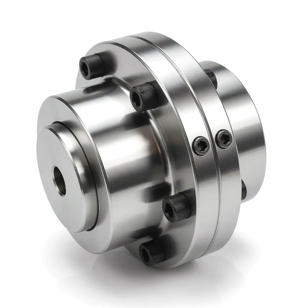
Every cement rotary kiln has an auxiliary drive system — commonly called the barring gear or inching drive — that rotates the kiln at a very low speed during maintenance periods, during heat-up from cold, and for short periods after shutdown when the shell must be kept turning to prevent it from bowing under its own weight due to thermal gradients. The coupling in the auxiliary drive train operates at low speed and low torque compared to the main drive, but it must engage and disengage reliably even when the main drive coupling is already connected to the kiln’s kinematic system. In Sheffield’s heavy industrial tradition, where continuous process plant reliability is a point of professional pride, the auxiliary drive coupling is viewed as a safety-critical component — if it fails to engage during a scheduled main drive outage, the kiln shell may sustain permanent distortion that requires enormously costly repair.
Flexible jaw couplings or elastomeric couplings are commonly specified for the auxiliary drive, selected for their inherent shock absorption during engagement at the instant when the barring gear motor starts and its pinion teeth engage the kiln main gear ring. The elastomeric insert in these couplings absorbs the engagement shock, preventing the torque spike from damaging the motor, its worm gear reducer, or the clutch mechanism connecting the barring gear to the main drive system. The coupling in the auxiliary drive position must also be selected to withstand the heat environment of the kiln drive area without the elastomeric element softening or swelling, which limits the maximum service temperature of elastomeric couplings to around 80 to 100 degrees Celsius in this location.
03
Application Scenario: Raw Mill and Cement Mill Drives
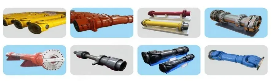
The cement production process includes large rotary grinding mills — the raw meal mill before the kiln and the cement mill after clinker discharge — that present coupling requirements that are related to, but distinct from, the kiln main drive itself. These horizontal grinding mills are driven by ring motors or by gearbox-and-pinion systems similar to the kiln, but the torque loading is characterised by frequent starts under high inertia, load variations as the grinding charge inside the mill shifts, and occasional shock loads when hard feed material passes through the mill. Gear couplings in the grinding mill application must therefore combine the misalignment accommodation needed for large rotating shells with the shock absorption and overload protection suited to intermittent heavy starting conditions.
UK cement plants operating in the limestone belt from Derbyshire down through the Cotswolds to Kent typically specify coupling designs for their mill drives that include thermal relief ports — small pressure-relief passages in the coupling sleeve that allow hot lubricant to vent and cool air to enter during heat-up cycles, preventing pressure build-up inside the sleeve that could force lubricant past the seal rings. This design feature extends seal life significantly in the heated environment of a cement plant, reducing lubricant loss and the associated contamination of the surrounding drive pit area.
04
Application Scenario: Kiln Cooling Fan and ID Fan Drives
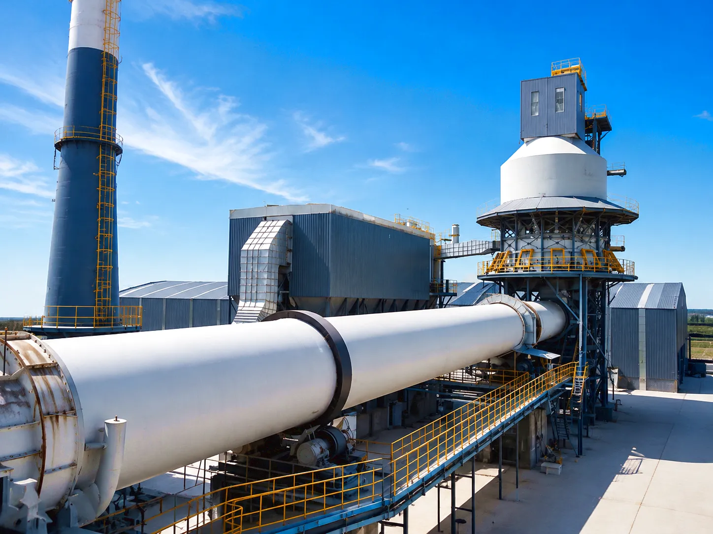
The clinker cooler fans and the kiln induced draught (ID) fans that manage the air flow through the cement burning system represent coupling applications where the dominant challenges are slightly different from the kiln main drive. Fan drives operate at higher rotational speeds — typically 500 to 1,500 rpm — and the coupling must handle both the misalignment between the motor and fan shafts and the torsional vibrations generated by the motor’s electrical system and by the aerodynamic unsteadiness of the fan impeller. These torsional vibrations, if not adequately attenuated, can fatigue-crack coupling elements and ultimately damage the fan shaft or motor shaft. Flexible disc couplings or torsionally soft jaw couplings are therefore often preferred for fan drives over the stiffer gear coupling, trading some misalignment accommodation capacity for better torsional vibration damping characteristics.
At larger cement plants such as those in the Buxton area of Derbyshire — which serve as major aggregate and cement supply hubs for the Northern England construction market — the ID fan drives may consume 2,000 to 5,000 kW of installed power, and their coupling selection affects both the fan’s vibration signature and its long-term shaft seal reliability. A poorly matched coupling that transmits excessive torsional vibrations through to the fan shaft accelerates shaft sleeve wear at the fan bearing positions, leading to premature bearing failure and unplanned shutdowns that cascade through the kiln’s thermal process, since changing combustion air flow disturbs the kiln’s temperature profile and clinker quality.
Featured Products for Cement Kiln Drive Applications
Precision-engineered coupling solutions suited to industrial rotary kiln environments
Flexibele koppeling
Flexibele balkkoppeling
Designed for precision shaft connection in medium-duty applications within cement plant auxiliary systems, the Flexible Beam Coupling absorbs vibration and accommodates angular and parallel misalignment through its helical-slot beam structure. Manufactured from high-grade stainless or aluminium alloy, it delivers consistent performance in dusty, thermally variable environments typical of cement processing facilities. Its zero-backlash characteristic makes it particularly suited to position-controlled auxiliary equipment within cement production lines.
Bekijk flexibele balkkoppeling →
Hoogwaardige koppeling
Schijfkoppeling
The Disc Coupling is an excellent choice for kiln fan drives and cement plant accessory systems where high-speed operation, high torsional stiffness, and the ability to transmit torque without lubrication are required. Its pack of thin, flexible metallic discs connects the two flanges of the coupling while accommodating angular and axial misalignment through disc deflection, without the micro-sliding contact that requires lubrication in gear couplings. This maintenance-free characteristic reduces operating costs on high-speed drives and eliminates the lubricant contamination risk that exists with grease-packed couplings operating near cement plant quality-sensitive equipment.
Schijfkoppeling bekijken →
Ever Power Manufacturing: Custom Coupling Solutions for Cement Industry
Precision manufacturing, deep customisation, and supply chain reliability for UK industrial buyers
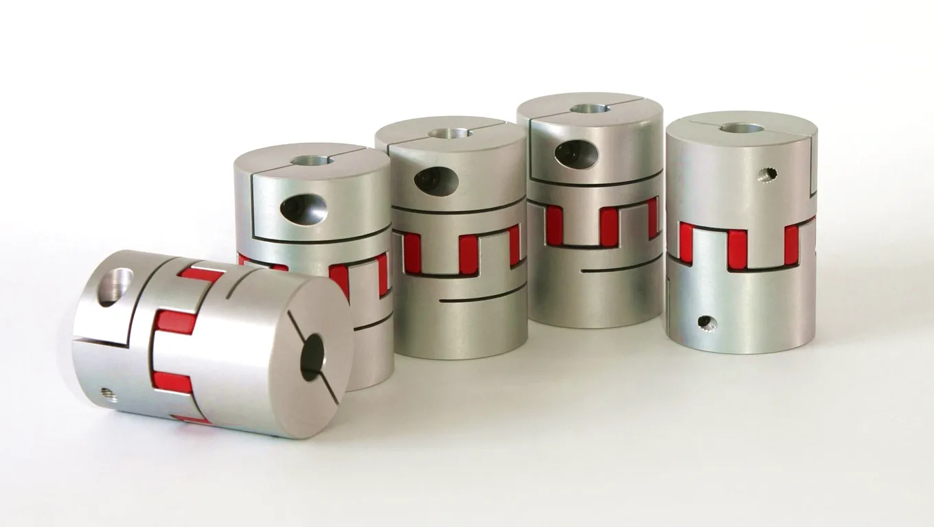 Ever Power has been engineering and manufacturing coupling solutions for heavy industrial applications for over two decades, with a dedicated portfolio for cement and mineral processing applications that reflects the specific technical demands of kiln drive environments. Our manufacturing facilities operate precision CNC gear grinding machines capable of producing crowned gear teeth to DIN 3960 tooth profile accuracy, with lead and profile corrections applied to individual tooth flanks to optimise the contact pattern under the specific misalignment conditions of each customer’s kiln drive. This level of customisation is not available from catalogue coupling suppliers and represents the technical depth that distinguishes an engineered coupling solution from a standard replacement part.
Our carburising furnaces operate with atmospheric carbon potential control to produce case depths and hardness profiles within tolerances of plus or minus 0.05 mm on case depth and plus or minus 2 HRC on surface hardness, across the full batch of parts being processed. This process control consistency ensures that every tooth in a kiln coupling set meets the same hardness specification, preventing the hot-spot fatigue initiation that occurs when a single tooth in the mesh is slightly softer than its neighbours. Material traceability from certified mill test reports is maintained for all alloy steel used in kiln-duty couplings, with certificates provided to UK customers as standard documentation for their plant maintenance records.
Ever Power’s application engineering team reviews every kiln coupling enquiry from UK customers against the actual drive configuration data: kiln shell diameter, shell length, inclination angle, reducer ratio, motor rating, and measured operational misalignment data where available. From this review, we produce a coupling selection calculation that demonstrates the safety factor on nominal torque, the proportion of misalignment capacity being utilised under worst-case operating conditions, and the predicted fatigue life of the gear teeth and flange bolts. This engineering analysis, provided with every custom order, gives UK plant engineering teams the technical justification they need for their internal approval processes when purchasing non-standard components outside their existing approved supplier lists.
ISO 9001
Quality Certified
DIN / AGMA
Standards Compliant
20+ Years
Industry Experience
Custom
Engineering Service
Customer Success Story: Ribblesdale Cement Plant, Clitheroe, Lancashire
How Ever Power resolved a recurring coupling failure that was costing an estimated £180,000 per year in unplanned downtime
Case Study | Cement Manufacturing | Clitheroe, Lancashire, UK
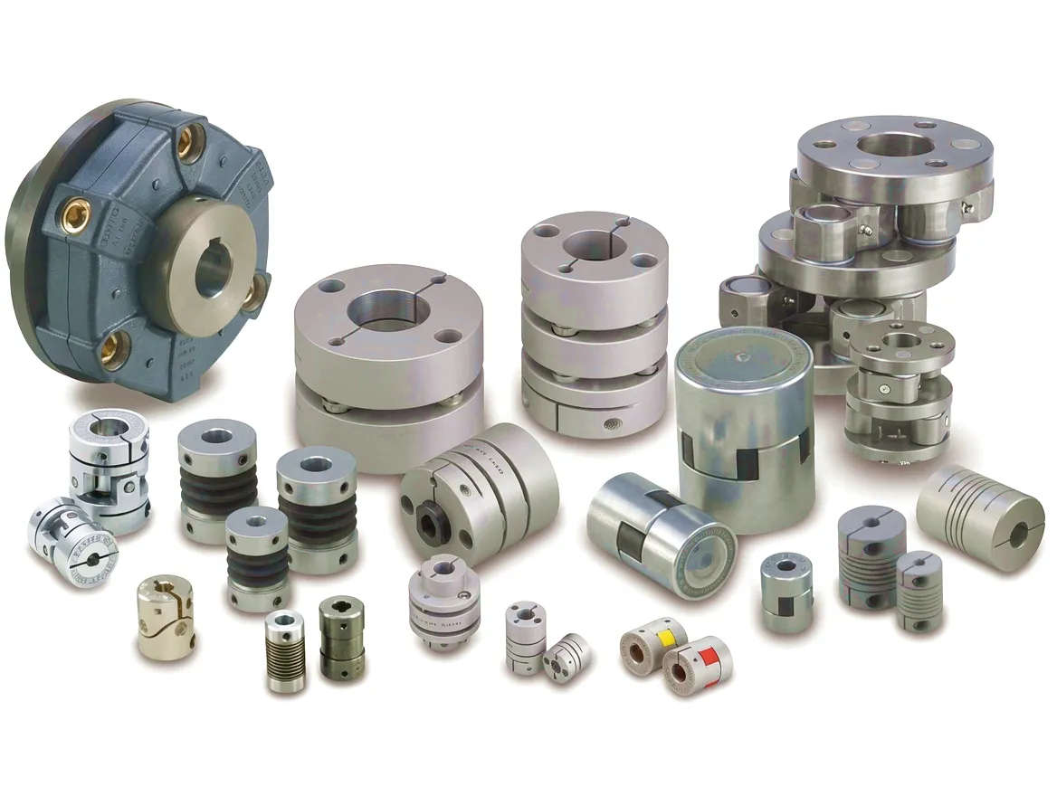
A major cement production facility in Clitheroe, Lancashire, operating two wet-process rotary kilns that supply clinker to concrete producers across the North West of England, was experiencing repeated coupling failures on the main drive of Kiln 2. The coupling — a gear coupling supplied by a European manufacturer — was failing at the gear tooth level, with tooth flank micro-pitting and progressive spalling developing within 12 to 18 months of installation. Each failure required a full kiln shutdown lasting approximately 36 hours for coupling removal and replacement, at a combined cost of lost production and emergency maintenance labour estimated at approximately £90,000 per event. With two to three events occurring per kiln per year, the total cost impact was reaching levels that justified a thorough engineering investigation.
The plant’s reliability engineering team engaged Ever Power following a referral from a sister plant in Birmingham that had previously resolved a similar issue with Ever Power’s assistance. Our application engineers visited the site, reviewed the existing coupling drawings, examined a failed coupling set, and conducted a detailed review of the kiln’s operational data including drive motor current logs which revealed periodic overcurrent spikes corresponding to specific kiln rotational positions. This analysis led to the identification of two contributing factors: the kiln’s shell had developed a slight oval distortion over years of service, generating a twice-per-revolution torque variation that the original coupling selection had not accounted for; and the coupling’s specified tooth crowning radius was insufficiently generous to handle the combination of thermal misalignment and this dynamic torque variation without initiating surface fatigue.
Ever Power engineered a replacement coupling set with a modified tooth crowning profile — using a spherical crowning geometry rather than the cylindrical crowning on the original design — which distributes contact load more evenly across the tooth face under the combined angular and radial misalignment of this specific installation. We also specified a higher-viscosity EP grease formulation to maintain the lubricant film thickness under the higher contact pressures resulting from the dynamic torque variation. The replacement coupling set was installed during a planned annual maintenance window in March, and the plant has since operated for 22 consecutive months without a coupling-related event. The plant’s maintenance team reports that the new coupling’s lubricant analysis remains clean at the 12-month interval, with no metal particle content above background levels.
Outcome Summary
£180k
Annual Saving (estimated)
Wat onze klanten zeggen
★★★★★
“The coupling Ever Power supplied for our Kiln 2 main drive has now been in service for nearly two years without any issue. What impressed us most was the depth of analysis their engineers provided before the order — they identified a tooth crowning mismatch that our own team had not caught, and the modified design they proposed has completely resolved the recurring tooth spalling problem that had been costing us tens of thousands of pounds per event. For a critical component of this nature, the technical engagement was as important as the product itself.”
James Hargreaves
Senior Reliability Engineer, Cement Plant — Clitheroe, Lancashire
★★★★★
“We specified Ever Power couplings for the rebuild of our raw mill and cement mill drives during a major plant overhaul in 2023, based on recommendations from industry contacts in Birmingham’s manufacturing sector. The material certifications and tooth inspection reports supplied with each coupling were comprehensive and exactly what our quality department required. Lead times were met, documentation was complete, and the couplings have performed without fault since commissioning. We have since added them to our approved component list for future purchases.”
Patricia Sandford
Plant Engineering Manager, Building Materials Group — West Midlands, UK
★★★★★
“Our kiln auxiliary barring drive had a history of elastomeric coupling failures that we attributed to the heat environment in the drive pit. Ever Power’s application team reviewed our installation and recommended a different elastomeric compound grade with a higher maximum service temperature rating, and also adjusted the coupling’s bore fitting to reduce the operating misalignment within the auxiliary drive. The modification cost was minimal compared to a standard replacement, and the failure interval has extended from 8 months to over 18 months on current service. I would recommend contacting their technical team early in the specification process.”
Robert Tanner
Maintenance Superintendent, Lime and Cement Operations — Buxton, Derbyshire
Veelgestelde vragen
Common questions from UK cement plant engineers about kiln drive couplings
What type of coupling is typically used on a cement rotary kiln main drive in the UK, and how does the selection process work? ›
The gear coupling is the standard choice for cement rotary kiln main drives in the UK. The selection process begins with the kiln’s design torque, calculated from motor rating and gearbox ratio, multiplied by a service factor that accounts for startup torque, cyclic loads, and shock loading. The coupling must then meet a minimum misalignment capacity based on the kiln’s expected thermal expansion and shell runout, derived from either design data or site measurements. Ever Power can provide a full selection calculation based on customer-supplied kiln data.
How much does a custom gear coupling for a cement kiln main drive cost, and what is the lead time for supply to a UK plant? ›
Pricing for custom kiln drive couplings varies significantly with torque rating, bore dimensions, and material specification. A medium-duty kiln coupling (30,000 to 100,000 N·m) typically ranges from £8,000 to £25,000 for a complete set including spacer shaft, while large kiln couplings may reach £40,000 to £80,000 or more depending on complexity. Lead times for custom-manufactured units are typically 8 to 16 weeks from order confirmation. Ever Power offers expedited manufacturing for urgent replacement orders from UK customers experiencing kiln downtime. Contact
[email protected] for a specific quotation.
Which coupling supplier in the UK or internationally can provide gear couplings rated for over 200,000 N·m for large cement kilns? ›
Several international specialist manufacturers supply very large kiln couplings to the UK market, including Ever Power, which produces custom gear couplings rated up to 500,000 N·m for the largest kiln main drives. Selection of the right supplier for this rating range should consider not just the rated torque but also the supplier’s ability to provide the engineering analysis, material certification, and dimensional accuracy verification that UK plant engineering and procurement teams require for non-standard components.
How often should the gear coupling on a cement rotary kiln main drive in Sheffield or Birmingham be relubricated, and what grease specification should be used? ›
Relubrication intervals for kiln main drive gear couplings in grease-packed service typically range from 6 to 18 months, depending on coupling peripheral speed, ambient temperature, and the quality of the coupling’s lip seal. A lithium complex or polyurea base grease with an NLGI 1.5 or 2 consistency and EP additive package rated to ISO 6743-9 CKP is recommended for most UK cement plant environments. Relubrication should always be performed during a planned kiln stop, and drained used grease should be submitted for particle count analysis to detect early-stage tooth wear.
What are the signs that the coupling on a cement kiln drive is failing, and when should a UK plant engineer schedule replacement? ›
Early warning signs of gear coupling deterioration on a cement kiln include increased vibration amplitude at the gearbox output bearing, metal particles in the coupling lubricant at relubrication, audible low-frequency clunking during kiln direction reversal or at startup, and abnormal temperature rise at the coupling body during sustained operation. Thermal imaging of the coupling during operation can detect hot spots that indicate concentrated load due to non-uniform tooth engagement. Any of these signs warrants inspection during the next planned kiln stop, and replacement should be scheduled if tooth spalling, flank cracking, or sleeve distortion is found during inspection.
Where can a UK cement plant procurement team get a competitive price quote for a replacement coupling for a 1980s or 1990s vintage rotary kiln drive? ›
For replacement couplings on older kilns where original manufacturer drawings may no longer be available, Ever Power offers a reverse-engineering service that produces a new coupling matching the original geometry from physical measurements of the existing coupling or from the kiln drive component drawings. UK procurement teams can initiate a quotation request by emailing
[email protected] with available drawings, photographs, and dimensional data from the existing coupling. Our team will prepare a competitive price proposal with full technical specification within 5 working days, suitable for submission through standard procurement approval processes.
Ever Power — Engineered for the Demands of UK Cement Industry
Specify Your Kiln Drive Coupling with Confidence
From selection calculation to custom manufacturing, Ever Power supports UK cement plant teams at every stage of the coupling replacement or upgrade process.
bewerkt door gzl