
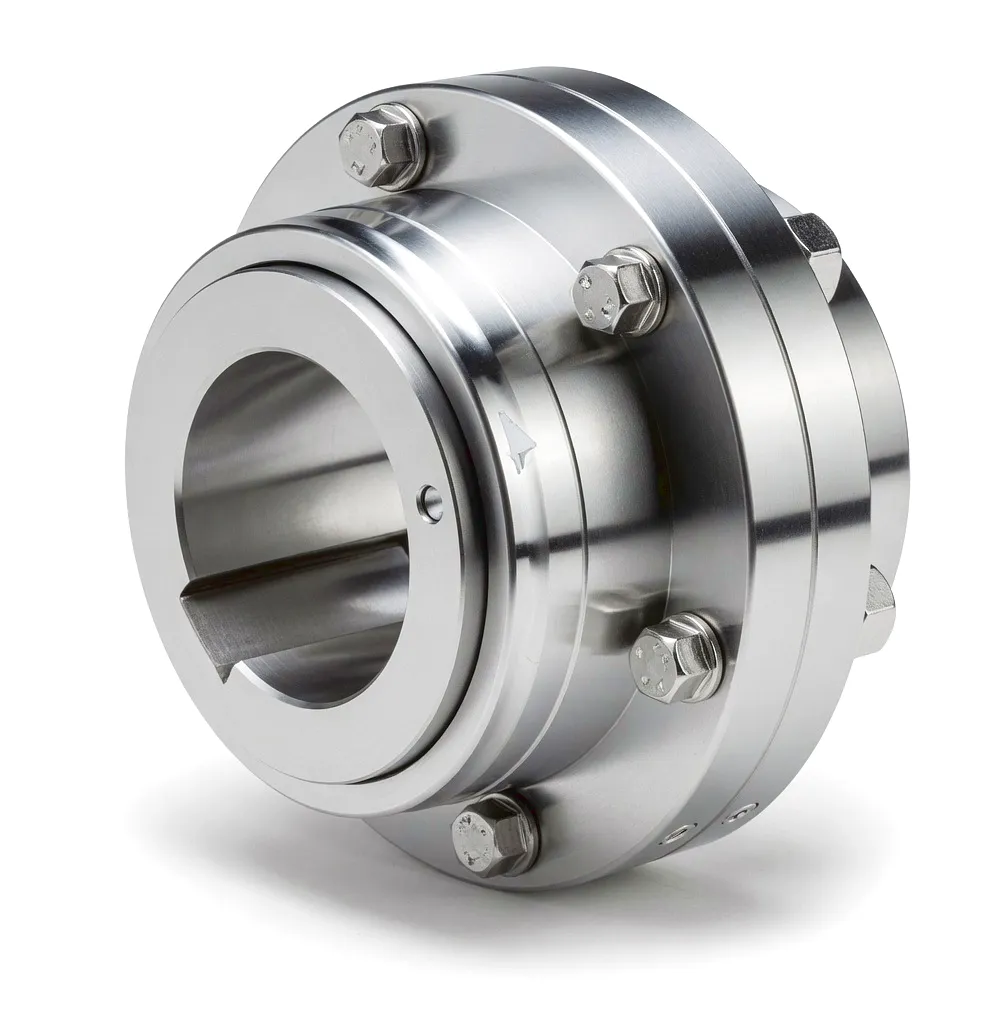
Thermal power generation sits at the backbone of the United Kingdom’s energy infrastructure. From the large coal-to-gas conversion plants repurposed across the Midlands to the modern combined-cycle gas turbine facilities serving grid operators in the North of England, every megawatt of electricity ultimately depends on one critical mechanical interface: the coupling that connects the steam turbine shaft to the generator rotor. This single component must handle power outputs that can exceed several hundred megawatts, operating continuously without scheduled downtime for months at a stretch. Unlike general industrial machinery where a brief interruption carries only productivity costs, an unplanned coupling failure in a baseload power station triggers grid instability, massive financial penalties under balancing mechanism contracts, and in some cases, cascading effects across regional distribution networks. The engineering demands placed on couplings in thermal power generation are, by any measure, among the most severe in modern mechanical engineering.
What makes this application unique is the combination of factors that no single engineering challenge alone would present. The turbine shaft spins at either 3,000 RPM (for 50 Hz grid synchronisation) or 1,500 RPM in larger multi-pole configurations, transmitting torques that can reach tens of thousands of Newton-metres. The operating temperatures at the turbine end can exceed 500°C, causing the rotor and casing assembly to expand thermally by several millimetres. The coupling must accommodate this thermal growth without imposing bending loads back onto the turbine bearings, which are already operating at the limit of their design envelope. Simultaneously, the generator end demands torsional stiffness to suppress resonant vibrations that could excite the rotor windings and lead to insulation failure. It is a set of competing requirements that has historically driven some of the most sophisticated coupling engineering in any sector.
Working Principle: How Couplings Bridge Turbine and Generator
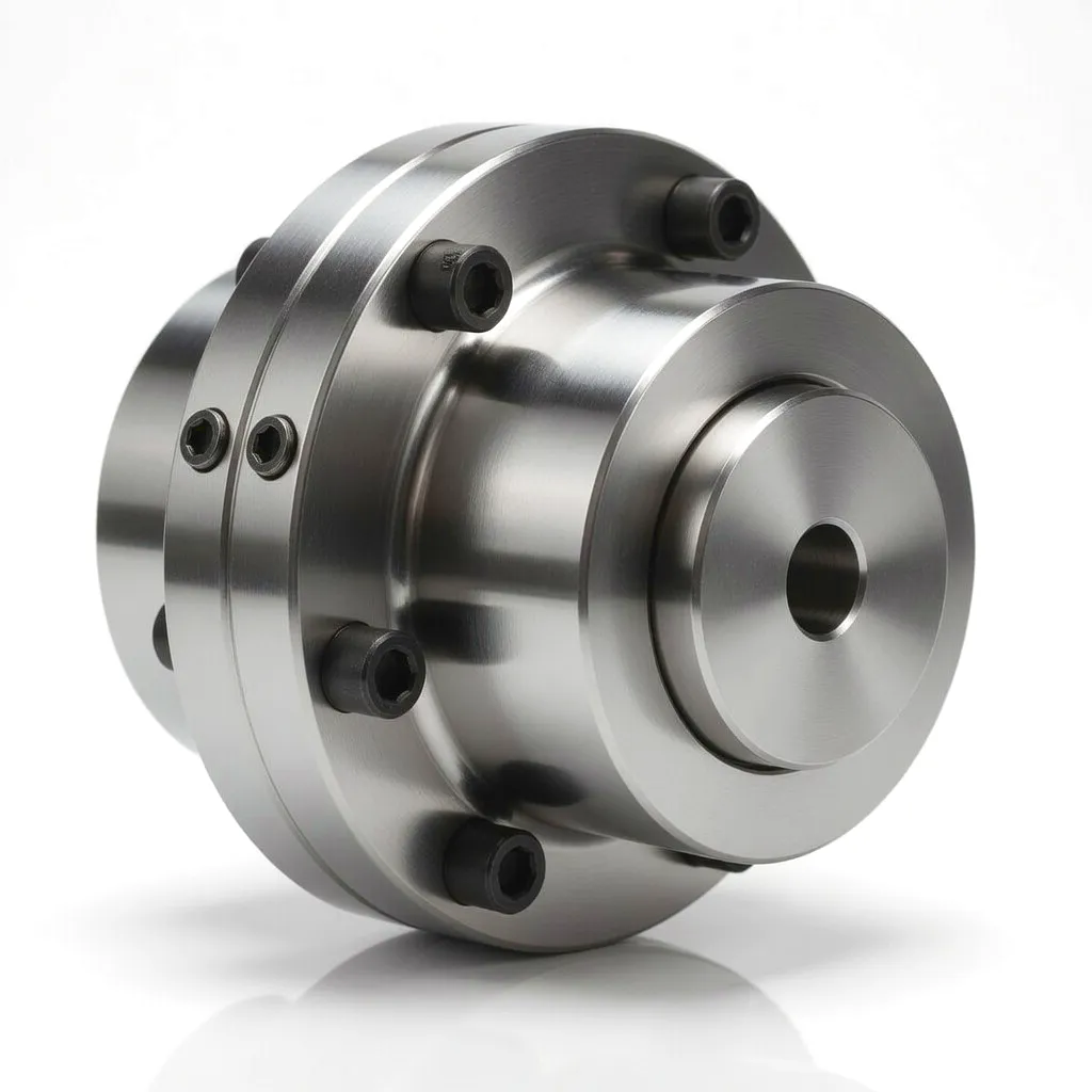
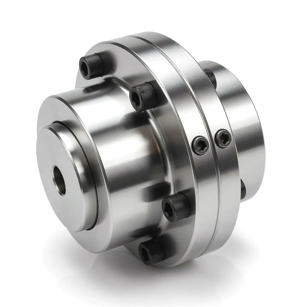
The coupling in a turbine-generator set functions as both a power transmitter and a mechanical buffer. On the transmission side, it must carry the full rated torque from the turbine output flange to the generator input shaft with negligible power loss and zero backlash under steady-state operation. Gear type couplings achieve this through precision-cut external gear teeth on the coupling hubs meshing with internal gear teeth on the coupling sleeves. The involute tooth profile distributes contact stress across multiple teeth simultaneously, allowing the coupling to transmit enormous torques within a compact envelope that suits the tight clearances of turbine hall floor layouts — a consideration particularly relevant in older UK power stations where the plant was originally designed around older, less thermally efficient equipment.
The misalignment accommodation mechanism is equally important. As the turbine casing heats from cold start to operating temperature, the turbine rotor rises and shifts axially relative to its cold-alignment position. In a large 500 MW unit, this thermal growth can amount to 3 to 5 millimetres of axial displacement and 1 to 2 millimetres of radial offset. The gear coupling tolerates these movements through the crowned tooth profile on the hub gear teeth — a slight barrel-shaped curvature that allows relative angular and axial motion between hub and sleeve without creating bending moments. The result is that the bearing housings on both the turbine and generator experience only the forces they were designed to carry, rather than the additional reactions that would arise from a rigid connection. This principle, though conceptually straightforward, requires extraordinary manufacturing precision to execute: the tooth crown radius, the lubricant clearances, and the gear tooth accuracy must all conform to tolerances measured in microns rather than thousandths of an inch.
Torsional dynamics represent the third dimension of the design problem. The turbine-generator rotor system is a distributed mass-spring system with multiple natural frequencies. If the coupling torsional stiffness places a resonant frequency within the operating speed range, the resulting vibration amplitudes can destroy the rotor within minutes. Coupling manufacturers work with turbine OEMs and generator manufacturers to tune the torsional stiffness of the coupling — adjusting tooth geometry, hub bore dimensions, and sleeve wall thickness — so that natural frequencies fall safely away from both running speed and its harmonics. This is not a catalogue-selection exercise; it is an engineering calculation that requires detailed modal analysis of the complete rotor train.
Core Materials: Engineering Alloys for Extreme Conditions
The primary material for coupling hubs and sleeves in power generation applications. 42CrMo4 delivers a tensile strength of 900–1,100 MPa after quench and temper treatment, combined with good fatigue resistance under alternating torsional loading. In the UK, this grade is supplied to BS EN ISO 683 standards and sourced from established mills in Sheffield and the wider Yorkshire steel corridor. For highest-demand applications, 34CrNiMo6 offers superior impact toughness at the temperature extremes encountered during cold-start transients.
The gear tooth surfaces undergo carburising or nitriding to achieve a surface hardness of 58–62 HRC while maintaining a tough core. This combination prevents pitting and micropitting under the Hertzian contact stresses that arise during torque surges — such as load rejection events when the generator is tripped from the grid. The case depth is precisely controlled to match the calculated contact fatigue life required for the specified overhaul interval, typically aligned with the station’s 10-year major outage schedule.
Gear couplings in this application are typically packed with high-viscosity grease or supplied with a circulating oil system fed from the turbine’s own lubrication circuit. Seal materials must withstand continuous exposure to oil mist at elevated temperature. Fluorocarbon (FKM) elastomeric seals are standard for temperatures above 120°C, while PTFE lip seals are preferred where chemical compatibility with turbine oil additives is a concern. Seal integrity directly affects coupling service life, and seal replacement is typically carried out at every major inspection.
Where the turbine and generator must be separated by a defined axial gap for bearing access or for generator rotor withdrawal, a spacer-type gear coupling is used. The spacer tube — typically manufactured from a seamless alloy steel tube or a precision-machined solid bar — must be dynamically balanced to the same G2.5 grade as the complete assembly. Its length and wall thickness are determined by critical speed analysis to ensure that the bending critical speed of the spacer itself lies well above the highest operating speed.

Product Advantages: Why Gear Couplings Dominate Power Generation
Gear couplings transmit higher torque per unit of outer diameter than any flexible coupling type. This is decisive in power station turbine halls where radial space around the shaft centreline is constrained by the turbine bearing pedestals and oil deflector housings. The ability to package massive torque capacity within the existing mechanical envelope allows for coupling upgrades on repowered units without civil engineering modifications.
Crowned gear teeth accommodate angular misalignment of up to 1.5° per gear mesh and axial displacement of several millimetres without imposing significant restoring forces. This is the primary reason gear couplings retain their market leadership in high-temperature turbomachinery applications, where competing elastomeric or disc coupling designs cannot match the misalignment range without compromising torque capacity or life expectancy.
Power station couplings are not replaced like wear parts — they are engineered to outlast multiple overhaul cycles. With correct material selection, precise gear geometry, and adequate lubrication, fatigue life exceeding 100,000 cumulative operating hours is a documented and contractually guaranteed performance target for major OEM supplies. This durability translates directly into reduced whole-life asset cost, a consideration that carries significant weight for UK power station asset managers working within National Grid capacity agreements.
Coupling assemblies for turbine-generator applications are dynamically balanced to G2.5 grade or better in accordance with ISO 21940. This balance quality limits vibration excitation from the coupling mass itself to levels that are negligible compared to the vibration floor of the rotor system. Achieving this balance grade requires the coupling manufacturer to operate precision CNC turning, grinding, and dedicated balancing machinery — a capital investment that distinguishes specialist suppliers from general industrial coupling vendors.
Well-designed gear couplings allow tooth condition inspection and grease replenishment without removing the coupling from the shaft. The split sleeve design enables the outer halves to be withdrawn axially for tooth inspection and cleaning while the hubs remain on the shaft. This capability cuts planned outage time significantly — a commercially critical advantage for UK power stations operating in a competitive capacity market where each hour of additional forced outage carries a measurable revenue cost.
Unlike fixed-element couplings, gear coupling torsional stiffness can be adjusted within a design by modifying the tooth number and module, the hub bore diameter, and the sleeve wall geometry. This configurability is used by coupling engineers to place the torsional natural frequencies of the rotor train at safe margins from running speed, half running speed, and electrical frequency excitation from the generator — without requiring redesign of the turbine or generator shaft itself.
Technical & Performance Parameters — Power Generation Couplings
| Parameter | Typisch bereik | Peak / Max | Notities |
|---|---|---|---|
| Nominaal koppel | 10,000 – 500,000 N·m | Up to 1,200,000 N·m | Dependent on module size, tooth count, and material grade |
| Maximale snelheid | 1,500 – 3,600 RPM | Up to 6,000 RPM | Higher speeds require tighter balance grade and reduced tooth crown |
| Hoekafwijkingscapaciteit | 0.5° – 1.0° per mesh | Up to 1.5° per mesh | Gear crown profile determines maximum angular offset capacity |
| Axiale verplaatsing | ±2 mm – ±8 mm | ±15 mm (spacer type) | Thermal growth compensation; axial buffer spring optional |
| Dynamische balansgraad | G2.5 (ISO 21940) | G1.0 on request | Balanced as complete assembly including hubs, sleeves, and spacer |
| Naafmateriaal | 42CrMo4 / 34CrNiMo6 | Stainless / Duplex on request | BS EN ISO 683 compliant; ultrasonic tested forgings |
| Tandoppervlaktehardheid | 58 – 62 HRC | Up to 64 HRC (nitrided) | Carburised, quenched, tempered, and ground after hardening |
| Bedrijfstemperatuur | -20°C to +120°C | Up to +150°C (FKM seal) | Seal and lubricant selection determines upper temperature limit |
| Design Service Life | 100,000 hours | 150,000 hours (premium grade) | Fatigue life; seals and lubricant refreshed at scheduled outages |
| Bore Diameter | 80 mm – 500 mm | Custom above 500 mm | Shrink-fit or keyway connection; interference fit torque verified by FEA |
Application Scenario 13: Thermal Power Unit Turbine-Generator Drive
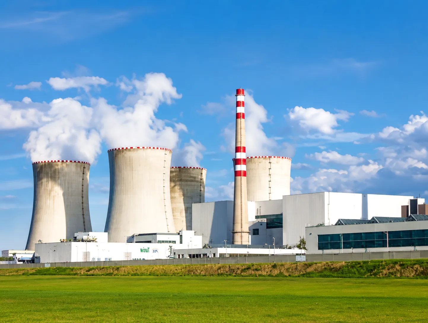
In thermal power generation, the connection between the steam turbine and the electrical generator represents the single most consequential mechanical interface in the entire plant. The turbine converts the thermal energy of high-pressure steam into rotational mechanical power; the generator converts that rotation into electricity. Between them, the coupling must carry the full shaft power — which in a large baseload plant operating at the margins of modern thermal efficiency can represent several hundred megawatts of continuous mechanical throughput. Getting this joint right is not an engineering nicety; it is the foundation upon which station availability, plant safety, and commercial performance are built.
The operating environment inside a turbine hall is challenging in ways that are easy to underestimate from the outside. The steam turbine casing operates at temperatures that cause the steel structure to expand measurably as it heats from cold start to operating condition. In a 300 MW turbine, the rotor centreline may rise by 2 to 4 mm and shift axially by 3 to 6 mm between cold alignment and hot running. If the coupling were a rigid flange connection, these movements would impose bending moments on the shaft that the turbine exhaust bearing was never designed to carry. The result, in practice, is premature bearing failure and, in severe cases, contact between rotating and stationary components inside the turbine casing — a catastrophic failure mode that requires months of repair and has historically triggered major insurance claims at UK power stations.

The gear coupling’s crowned tooth geometry provides the solution. As the turbine rotor shifts in its running position, the coupling hubs on each side simply rock through a small angle relative to the coupling sleeves. The contact pattern across the crowned teeth remains distributed and the forces transmitted back to the shaft bearings remain within design limits. This is not a passive accommodation — the coupling is continuously adjusting to the thermal state of the machine. During a warm start following a brief outage, the rotor may traverse its full thermal movement range in under thirty minutes, placing particular demands on the tooth crown profile and the lubrication film between the meshing surfaces. It is during these transient periods that inadequate coupling design most commonly reveals itself through elevated vibration signatures on the turbine supervisory instrumentation.
Speed-related demands reinforce the case for precision manufacturing. UK grid-connected generators run at a fixed synchronous speed of 3,000 RPM for two-pole machines, and any vibration in the coupling at this speed or its harmonics will feed directly into the generator vibration measurement points. Station management teams monitoring vibration continuously via on-line condition monitoring systems will raise alarms at vibration levels that would be unremarkable in many other industrial contexts. A coupling that produces a once-per-revolution vibration excitation of even a few microns of displacement amplitude at shaft speed can, over time, contribute to winding insulation fatigue in the generator rotor and trigger a costly forced outage for rewinding.
Further Industrial Application Scenarios
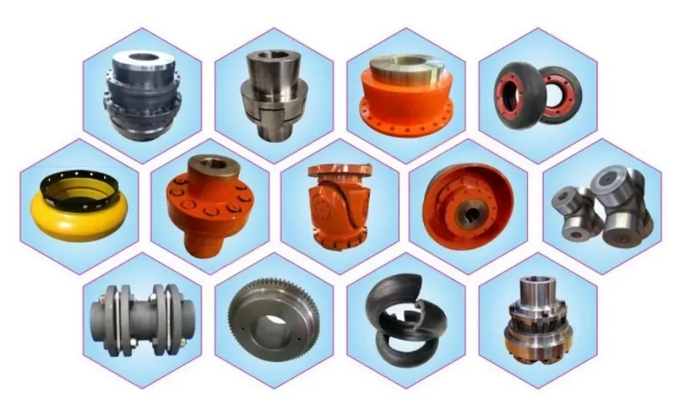
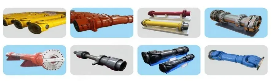
Ever Power: Precision Manufacturing & Custom Coupling Solutions
Ever Power has built its reputation in the power transmission sector on a straightforward proposition: every coupling we supply is engineered for the specific duty it will face, not selected from a standard catalogue and retrofitted to an application that deserves better. Our manufacturing capability encompasses the full range of coupling technologies required by the thermal power generation and heavy industrial sectors, from compact gear couplings for pump and compressor drives to large-bore, high-torque turbine-generator coupling assemblies with custom spacer arrangements. The investment Ever Power has made in precision CNC turning and gear cutting centres, dedicated gear grinding machines capable of achieving DIN 5 or better tooth accuracy, and a dynamic balancing facility rated to handle assemblies of up to 2,000 kg means that we can manufacture complete coupling assemblies that meet the most stringent OEM and station operator specifications.
Customisation capability at Ever Power extends well beyond changing a bore diameter. Our engineering team regularly works with station engineers, plant managers, and rotating equipment specialists at UK power operators to develop solutions where no standard product exists. This includes couplings with non-standard tooth geometries to achieve a specific torsional stiffness target identified in a rotor dynamic study; couplings with extended spacer lengths to provide generator rotor withdrawal clearance within a confined turbine hall layout; and couplings with integral torque-limiting elements where protection against motor or generator fault currents is a design requirement. Every custom project begins with a detailed engineering review, proceeds through finite element stress analysis of the hub bore interface and tooth root stress, and concludes with comprehensive dimensional inspection and witnessed dynamic balance testing before despatch.
Supply chain reliability is a commitment that Ever Power backs with manufacturing infrastructure rather than promises. All forgings are sourced from qualified mills operating to EN 10228 ultrasonic testing standards, with full material traceability from heat certificate to finished component. Heat treatment is conducted in-house on calibrated furnaces with continuous temperature recording, ensuring that the specified material properties are achieved consistently across production batches. Before any coupling leaves our facility, each assembly undergoes comprehensive final inspection including gear tooth contact pattern verification, dimensional checks against the approved drawing, and — for all power generation couplings — dynamic balance confirmation on our purpose-built balancing machine. Documentation packages including material certificates, heat treatment records, inspection reports, and balance certificates are provided as standard, meeting the traceability requirements of UK power station quality management systems.
UK customers working on plant modification projects, replacement coupling sourcing for ageing turbine sets, or new plant commissioning programmes can reach our technical sales team directly to discuss requirements, timeline, and pricing. We routinely provide same-day quotation responses for standard enquiries and commit to detailed engineering proposals for custom projects within five working days. Our logistics arrangements support delivery to power stations across England, Scotland, and Wales, with expedited options available for urgent plant availability situations.
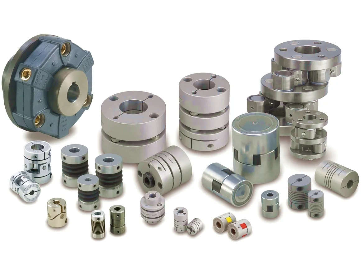
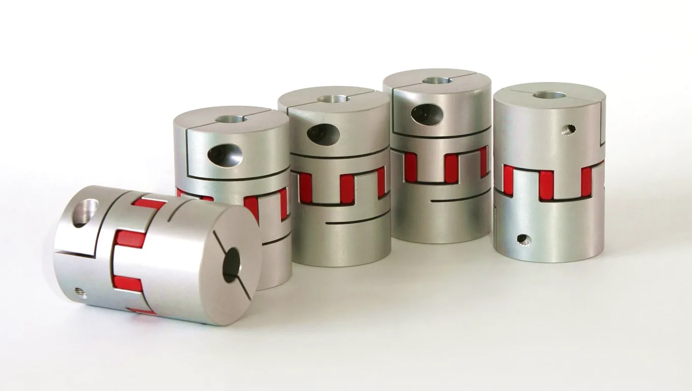
Featured Ever Power Coupling Products
Customer Success Story: Nottinghamshire Combined-Cycle Power Station Repowering

A combined-cycle gas turbine (CCGT) facility operating in Nottinghamshire, England, undertook a major repowering programme to upgrade its steam turbine section from an older single-shaft configuration to a more thermally efficient multi-shaft arrangement. The project involved replacing the existing turbine-generator coupling on the steam turbine train, which had accumulated over 85,000 hours of service and was approaching the end of its certified design life. The station’s maintenance manager — working with constraints that included a narrow outage window between capacity market delivery obligations, limited crane access in the turbine hall due to the ongoing civil modifications, and a requirement for the replacement coupling to exactly match the existing shaft bore diameters and coupling bolt circle dimensions — approached Ever Power with a detailed specification package.
Ever Power’s engineering team reviewed the specification and identified that a direct dimensional replacement was achievable within the standard manufacturing portfolio, but that the torsional stiffness of the new assembly would need to be verified against the updated rotordynamic model for the modified turbine train — the addition of a new LP turbine section had changed the mass distribution along the rotor. Our engineers collaborated directly with the station’s rotating equipment consultant to run a torsional analysis using the coupling torsional stiffness data from the Ever Power design model, confirming that the selected coupling configuration placed the first torsional natural frequency at a safe margin above the running speed and all relevant electrical frequency forcing functions.
Manufacturing was completed within six weeks from order placement. The coupling hubs were machined from 42CrMo4 forgings with full EN 10228 ultrasonic test certificates. Gear teeth were carburised, quenched, tempered, and ground to DIN 5 accuracy, with crowned tooth profiles machined to the crown radius specified in the engineering analysis. The complete assembly — comprising two hubs, two sleeves, and a spacer tube — was dynamically balanced as a complete unit on our balancing machine, achieving a residual imbalance of less than G1.5 against the G2.5 contractual requirement. The documentation package included all material certificates, heat treatment records, dimensional inspection reports, and the balance test report, compiled in the station’s required format.
Delivery was made to the station in Nottinghamshire with twelve days to spare before the outage commencement date, allowing the maintenance team to verify dimensions against the shaft and prepare the installation tooling in advance. The coupling was installed during the planned outage window, and the machine was returned to service on schedule. At six months following return to service, the station’s condition monitoring data showed vibration levels at the turbine and generator bearing housings that were measurably lower than those recorded before the replacement — a result attributable to the tighter dynamic balance grade of the new Ever Power coupling assembly compared to the worn original.
“The dimensional accuracy of the replacement coupling from Ever Power was exceptional. It dropped straight onto the shaft with the specified interference fit first time, without any reworking. The balance quality meant our vibration readings after first synchronisation were significantly better than pre-outage levels, which was frankly beyond our expectations for a replacement item.”
“What distinguished Ever Power from other suppliers we approached was their willingness to engage with the torsional analysis at the front-end of the project. Most coupling vendors just quote you a catalogue size. The fact that Ever Power could work through the rotordynamic implications of our modified turbine configuration alongside our own consultant gave us real confidence in the engineering basis of the selection.”
“Delivery was ahead of schedule and the documentation package was comprehensive and formatted to the standard our quality management system requires. The technical support during the installation — Ever Power had an engineer available by phone throughout the coupling installation day — was genuinely useful when we encountered a minor question about the torquing sequence for the spacer bolts. A supplier that actually supports you through the installation phase is rarer than it should be.”
Veelgestelde vragen
This article reflects industrial engineering knowledge as applied to UK power generation infrastructure. Technical parameters are representative of typical gear coupling performance in thermal power applications. For project-specific design, consult a qualified rotating equipment engineer. edit by gzl